


6. Connect the power plug of the host machine to the
outlet.
7. Turn ON the main power switch.
8. Turn ON the heater switch.
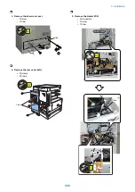
■ Installation of Reader Heater (For
iR2545/2535 series)
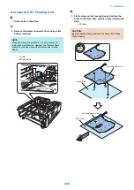
1. Move the drive belt in the arrow direction to shift the
CCD unit to the center.
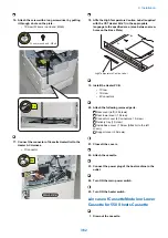
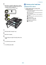
2. Install the 2 Wire Saddles (small), and then install the
Reader Heater (left side).
• 1 Connector
• 1 Screw
• 2 Wire saddles
1x
1x
2x
Binding; M4x6
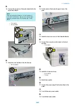
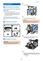
3. Install the 1 Wire Saddle (small), and then install the
Reader Heater (right side).
• 1 Connector
• 1 Screw
• 1 Wire saddle
1x
1x
Binding; M4x6
1x
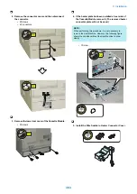
4. Attach the following removed parts.
Platen glass
Glass retainer (right) (2 Screws)
Rear lower cover (1 Screw)
Connector cover (1 Screw)
Left rear cover (3 Screws)
Left face cover (1 Screw)
Rear cover (left) (2 Screws)
Rear cover (right) (3 Screws)
5. Connect the power plug of the host machine to the
outlet.
6. Turn ON the main power switch.
7. Turn ON the heater switch.
9. Installation
353
Summary of Contents for imageRUNNER 2525 Series
Page 1: ...Revision 9 0 imageRUNNER 2530 2525 2520 Series Service Manual ...
Page 62: ...No Part name 3 Laser unit 2 Technical Explanation 52 ...
Page 119: ...Periodical Service 3 Consumable Parts and Cleaning Parts 110 Cleaning Parts 115 ...
Page 125: ...Cleaning Parts Fixing guide Transfer guide 3 Periodical Service 115 ...
Page 136: ...List of Sensors S18 S17 S16 TS2 HU1 S9 S8 S19 TS1 S11 S12 4 Disassembly Assembly 126 ...
Page 165: ...5 Remove the idler gear 1 claw 1x 4 Disassembly Assembly 155 ...
Page 172: ... 1 4 2 3 2 2 Remove the scanner motor 4 screws 4x 4 Disassembly Assembly 162 ...
Page 186: ...3 Remove the RAM PCB Release the hook 4 Disassembly Assembly 176 ...
Page 187: ...Adjustment 5 Overview 178 Basic Adjustment 180 Adjustment when Replacing the Parts 182 ...
Page 209: ...Error Jam Alarm 7 Outline 200 Error Code 201 Jam Code 213 Alarm Code 219 ...
Page 231: ...Service Mode 8 Overview 222 Details of Service Mode 225 Remote UI Service Mode 302 ...
Page 314: ...Example of report display 8 Service Mode 304 ...
Page 387: ...APPENDICES Service Tools 378 General Circuit Diagram 379 ...