


Chapter 7
287
Fixture Simulator
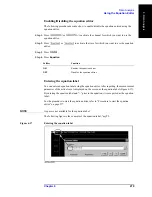
Determining Characteristics After Adding a Matching Circuit
7
. F
ixt
ur
e
Sim
ula
to
r
Determining Characteristics After Adding a Matching
Circuit
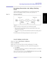
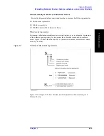
Using the matching circuit embedding function, you can easily obtain the resulting
characteristics after adding a matching circuit for each test port (Figure 7-4).
Figure 7-4
Matching circuit function
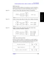
Define the matching circuit to be added by one of the following methods:
•
Select one of the five predetermined circuit models and specify the values for the
elements in the circuit model.
•
Use a user file (in two-port Touchstone data format) that defines the matching circuit to
be added.
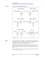
The circuit models used for defining matching circuits are shown in Figure 7-5.
Using the Matching Circuit Function
Step 1.
Press
-
Fixture Simulator - Port Matching
.
Step 2.
Press
Select Port
.
Step 3.
Press
1
,
2
,
3
, or
4
to select the port to which a matching circuit is to be added.
Step 4.
To add a matching circuit defined in a user file, execute the following operations:
a.
Press
User File
.
b.
In the dialog box that appears, select the two-port Touchstone data file (.s2p format) for
the matching circuit to be added.
Once a user file is specified, the selection of
Select Circuit
automatically changes to
User
.
In this case, you do not need to execute Step 5 and Step 6.
Summary of Contents for E5070B
Page 6: ......
Page 30: ...24 Contents ...
Page 34: ...28 Chapter1 Precautions Before contacting us ...
Page 286: ...280 Chapter6 Data Analysis Using the Equation Editor ...
Page 430: ...424 Chapter12 Optimizing Measurements Performing a Segment by Segment Sweep segment sweep ...
Page 538: ...532 Chapter15 Measurement Examples Executing Power Calibration ...
Page 634: ...628 AppendixB Troubleshooting Warning Message ...
Page 732: ...726 AppendixD Softkey Functions Trigger Menu ...
Page 740: ...734 AppendixE General Principles of Operation Data Processing ...
Page 760: ...754 AppendixF Replacing the 8753ES with the E5070B E5071B Comparing Functions ...


