


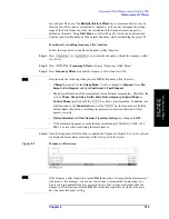


Chapter 8
315
Frequency-Offset Measurement (Option 008)
Measurement of Mixers
8. Fre
q
uency
Of
fset
Me
asur
eme
nt
(Option 0
08)
for each port. The use of the
Multiplier
/
Divisor
/
Offset
key is recommended as a rule. In
this way, the offset value is automatically retained even if you have changed the setting
range of the basic frequency, since the correlation of the frequencies among ports is
defined as a formula. Using
Start
/
Stop
key will set M and O, which can be determined
from the specified frequency and the normal frequency, while maintaining the preset D.
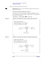
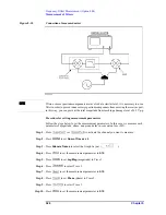
Procedures for enabling frequency-offset function
Follow the steps below to enable the frequency-offset function.
Step 1.
Press
(or
) to activate the channel on which the frequency-offset
is to be set.
Step 2.
Press
-
Frequency Offset
to display “Frequency Offset Menu.”
Step 3.
Press
Frequency Offset
to enable the frequency-offset function (ON).
NOTE
Keep in mind the following when you turn
ON
the frequency-offset function:
•
If
Swept
is selected for the
Sweep Mode
, it will be changed to
Stepped
(from
Std
Swept
to
Std Stepped
, and from
Fast Swept
to
Fast Stepped
).
•
The phase information of the measurement value becomes meaningless. Therefore, the
view of
Phase
,
Group Delay
,
Smith
,
Polar, Real
,
Imaginary
,
Expand Phase
or
Positive Phase
specified with the
key has no actual meaning. In addition, any
other function in the
Conversion
menu of the
key that cannot be calculated
without phase information, including the parameter conversion function, will not
operate correctly.
•
Fixture Simulator
and
Time Domain
(
Transform
,
Gating
) are changed to
OFF
.
•
If the measured frequency exceeds the measurable range (300 kHz to 3 GHz, or 8.5
GHz), an error will occur during the measurement.
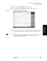
Step 4.
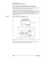
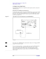
Once the frequency-offset function is enabled, the frequencies (Figure 8-2) set at each port
are displayed for each measured trace in the lower part of the screen.
Figure 8-2
Frequency-offset sweep
NOTE
If the frequency-offset function is turned
ON
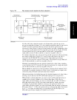
, the number of sweeps during measurement
will increase. For example, you can use two sweeps to measure the S-parameters of a
2-port setup in a normal frequency sweep; however, four sweeps are needed when the
frequency-offset function is turned
ON
. This holds true regardless of whether the ports
have the same frequency setting.
Summary of Contents for E5070B
Page 6: ......
Page 30: ...24 Contents ...
Page 34: ...28 Chapter1 Precautions Before contacting us ...
Page 286: ...280 Chapter6 Data Analysis Using the Equation Editor ...
Page 430: ...424 Chapter12 Optimizing Measurements Performing a Segment by Segment Sweep segment sweep ...
Page 538: ...532 Chapter15 Measurement Examples Executing Power Calibration ...
Page 634: ...628 AppendixB Troubleshooting Warning Message ...
Page 732: ...726 AppendixD Softkey Functions Trigger Menu ...
Page 740: ...734 AppendixE General Principles of Operation Data Processing ...
Page 760: ...754 AppendixF Replacing the 8753ES with the E5070B E5071B Comparing Functions ...


