


56
Chapter 2
Overview of Functions
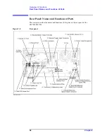
Rear Panel: Names and Functions of Parts
8. Power Cable Receptacle (to LINE)
The receptacle (outlet) to which the power cable is connected.
NOTE
To connect the device to a power source (outlet), use the supplied three-prong power cable
with a ground conductor.
The plug attached to the power cable (on the power outlet side or device side of the cable)
serves as the disconnecting device (device that cuts off power supply) of the
E5070B/E5071B. When the power supply must be cut off to avoid such danger as electric
shock, pull out the power cable plug (on the power outlet side or device side of the cable).
For the procedure for turning off the mains in normal use, see the description in “1.
Standby Switch” on page 31.
For more on the power supply, see Chapter 2 “Installation” in the Installation and Quick
Start Guide.
9. High Stability Frequency Reference Output Connector (Ref Oven,
Option 1E5 only)
When Option 1E5 (high stability frequency reference) is installed, the reference signal is
output from this connector.
Connector type: BNC connector, female
Output signal (Nominal): 10 MHz, +0 dBm
±
3 dB
NOTE
When Option 1E5 (high stability frequency reference) is installed, connect this connector
to the “10. External Reference Signal Input Connector (Ref In)” on page 56 by using the
BNC(m)-BNC(m) cable included with the option.
10. External Reference Signal Input Connector (Ref In)
The reference signal input connector for phase-locking the measurement signal from the
E5070B/E5071B to the external frequency reference signal. Inputting the reference signal
to this connector improves the accuracy and frequency stability of the measurement signal
from the E5070B/E5071B.
Connector type: BNC connector, female
Input signal (Nominal): 10 MHz
±
10 ppm, +0 dBm
±
3 dB
NOTE
When the frequency reference signal is input to this connector, the measurement signal
from the E5070B/E5071B is automatically phase-locked to the reference signal. When an
input signal is not present, the frequency reference signal inside the E5070B/E5071B is
automatically used. The
ExtRef
on the instrument status bar is displayed in blue when the
system is phase-locked to the external reference signal and in gray when not phase-locked.
When using Option 1E5 (high stability frequency reference), connect this connector to the
“9. High Stability Frequency Reference Output Connector (Ref Oven, Option 1E5 only)”
on page 56 by using the BNC(m)-BNC(m) cable included with the option.
Summary of Contents for E5070B
Page 6: ......
Page 30: ...24 Contents ...
Page 34: ...28 Chapter1 Precautions Before contacting us ...
Page 286: ...280 Chapter6 Data Analysis Using the Equation Editor ...
Page 430: ...424 Chapter12 Optimizing Measurements Performing a Segment by Segment Sweep segment sweep ...
Page 538: ...532 Chapter15 Measurement Examples Executing Power Calibration ...
Page 634: ...628 AppendixB Troubleshooting Warning Message ...
Page 732: ...726 AppendixD Softkey Functions Trigger Menu ...
Page 740: ...734 AppendixE General Principles of Operation Data Processing ...
Page 760: ...754 AppendixF Replacing the 8753ES with the E5070B E5071B Comparing Functions ...


