


68
Chapter 3
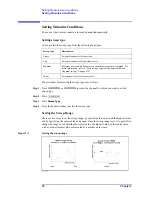
Setting Measurement Conditions
Setting Channels and Traces
IF bandwidth
√
-
IF Bandwidth
Calibration
√
Marker
√
(
*3
)
Analysis
Fixture simulator
√
(
*4
)
-
Fixture Simulator
Time domain
√
-
Gating
-
Transform
Parameter conversion
√
-
Conversion
Limit test
√
-
Limit Test
Saving and recalling data
√
Macro
√
System
Printing/Saving display
Screen/Beeper/GRIB settings/Network
Settings/Date & Time/Key
Lock/Backlight/Firmware
Revision/Service menu
√
Preset
√
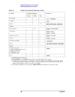
*1.
Hold All Channels
for the analyzer.
*2.
Auto Scale All
and scale
Divisions
must be set up in rectangular form for each channel.
*3.Turning the marker table display on or off applies to the entire analyzer. On the other hand, the sweep range setting
of the marker must be performed for each channel. In the preset condition, marker coupling is enabled and marker
settings and movements are effective for all traces on a channel.
*4.The balanced-unbalanced conversion function (
BalUn ON/OFF
) must be turned on or off for each trace.
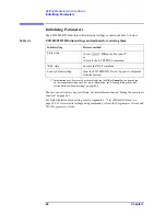
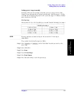
Table 3-2
Parameters and setup items they control
Parameter
Controlled Setup Items
Setup Key(s)
Analyzer
Channel
Trace
Summary of Contents for E5070B
Page 6: ......
Page 30: ...24 Contents ...
Page 34: ...28 Chapter1 Precautions Before contacting us ...
Page 286: ...280 Chapter6 Data Analysis Using the Equation Editor ...
Page 430: ...424 Chapter12 Optimizing Measurements Performing a Segment by Segment Sweep segment sweep ...
Page 538: ...532 Chapter15 Measurement Examples Executing Power Calibration ...
Page 634: ...628 AppendixB Troubleshooting Warning Message ...
Page 732: ...726 AppendixD Softkey Functions Trigger Menu ...
Page 740: ...734 AppendixE General Principles of Operation Data Processing ...
Page 760: ...754 AppendixF Replacing the 8753ES with the E5070B E5071B Comparing Functions ...


