


Appendix D
713
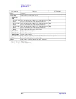
Softkey Functions
Scale Menu
D. Sof
tke
y
Fu
nctions
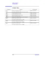
Scale Menu
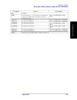
Key Operation
Function
SCPI Command
Displays softkeys for adjusting scales.
Auto Scale
Automatically adjusts scales for the active trace.
:DISP:WIND{1-16}:TRAC{1-16}:Y:AU
TO
Auto Scale All
Automatically adjusts scales for all traces within the active channel.
None
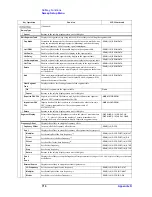
Divisions
Defines the number of divisions on the Y-axis of a rectangular display
format. An even number from 4 to 30 must be used. Once set, it is then
applied to all traces displayed in any rectangular display format within that
channel.
:DISP:WIND{1-16}:TRAC{1-16}:Y:DIV
Scale/Div
In a rectangular format, defines the number of increments per division on
the Y-axis. In the Smith chart format or polar format, defines the range (the
displacement of the outermost circle). The setting applies to the active trace
only.
:DISP:WIND{1-16}:TRAC{1-16}:Y:PDI
V
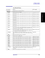
Reference Position
Defines the position of the reference line on a rectangular display format.
The position must be defined by using numbers assigned to the Y-axis
between 0 (the origin, the X-axis) and the number of divisions (the highest
scale). This setting applies only to the active trace. The reference line can
also be moved by performing a drag-and-drop operation (pressing the
mouse button on the object to be moved and releasing the button after
dragging it to the desired position) on one of the reference line pointers (
and ).
:DISP:WIND{1-16}:TRAC{1-16}:Y:RP
OS
Reference Value
Defines the value corresponding to the reference line on a rectangular
display format. The setting applies only to the active trace.
:DISP:WIND{1-16}:TRAC{1-16}:Y:RL
EV
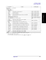
Marker
Æ
Reference
Changes the value of the reference line to the response value of the active
marker. The same function is also accessible from the “Marker Function
Menu” on page 697.
:CALC{1-16}:MARK{1-10}:SET
Electrical Delay
Sets the electrical delay (second) and media type to be added for correcting a phase delay .
Electrical Delay
Sets an electrical delay to the active trace. This function simulates the
addition or deletion of a variable length lossless transfer line against the
input of a receiver. It can be used to compensate for the electrical length of
cables inside the DUT. Although the unit used is seconds, the length
(meters) will be displayed in parentheses next to the input box based on the
velocity coefficient used at the time.
:CALC{1-16}:CORR:EDEL:TIME
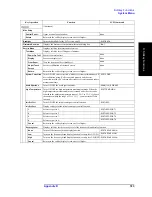
Media
Sets the media type required for the calculation to correct a phase delay.
:CALC{1-16}:CORR:EDEL:MED
Cutoff Frequency
Sets the cut-off frequency when the media type is waveguide.
:CALC{1-16}:CORR:EDEL:WGC
Phase Offset
Sets the values to be added or subtracted in phase measurement (phase
offset) (×).
:CALC{1-16}:CORR:OFFS:PHAS
Return
Returns to the “E5070B/E5071B Menu (Top Menu)” on page 646.
Summary of Contents for E5070B
Page 6: ......
Page 30: ...24 Contents ...
Page 34: ...28 Chapter1 Precautions Before contacting us ...
Page 286: ...280 Chapter6 Data Analysis Using the Equation Editor ...
Page 430: ...424 Chapter12 Optimizing Measurements Performing a Segment by Segment Sweep segment sweep ...
Page 538: ...532 Chapter15 Measurement Examples Executing Power Calibration ...
Page 634: ...628 AppendixB Troubleshooting Warning Message ...
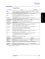
Page 732: ...726 AppendixD Softkey Functions Trigger Menu ...
Page 740: ...734 AppendixE General Principles of Operation Data Processing ...
Page 760: ...754 AppendixF Replacing the 8753ES with the E5070B E5071B Comparing Functions ...


