


238
Chapter 4
Calibration
Scalar-Mixer Calibration
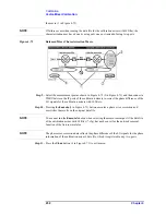
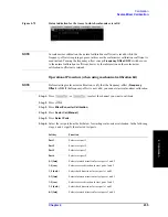
Figure 4-77
Connection of power sensor
Step 28.
Press
Port x@Freq x
.
Step 29.
Press
Port x@Freq y
.
Step 30.
Press
Port y@Freq x
.
Step 31.
Press
Port y@Freq y
.
Step 32.
Press
Return
.
Step 33.
Press
Done
to exit the scalar-mixer calibration. This step allows the calibration coefficient
to be calculated, turning on the error correction function automatically.
Operational procedure (when using ECal module)
To start calibration, refer to “Operational Procedure (when using mechanical calibration
kit)” on page 235; the steps up to Step 7 in that procedure are common to this procedure.
Step 1.
Select a test port and then press
Power Meter
.
NOTE
In scalar-mixer calibration, the power meter is used. For more information on how to set
the power meter, see “Preparing to control the power meter” on page 210.
Step 2.
Press
Use Sensor
. Each time the key is pressed, Channels A and B switch over alternately.
If you are using a one-channel power meter, select Channel A.
Step 3.
Connect the power sensor for the selected channel to the selected port, as shown in Figure
4-78.
Summary of Contents for E5070B
Page 6: ......
Page 30: ...24 Contents ...
Page 34: ...28 Chapter1 Precautions Before contacting us ...
Page 286: ...280 Chapter6 Data Analysis Using the Equation Editor ...
Page 430: ...424 Chapter12 Optimizing Measurements Performing a Segment by Segment Sweep segment sweep ...
Page 538: ...532 Chapter15 Measurement Examples Executing Power Calibration ...
Page 634: ...628 AppendixB Troubleshooting Warning Message ...
Page 732: ...726 AppendixD Softkey Functions Trigger Menu ...
Page 740: ...734 AppendixE General Principles of Operation Data Processing ...
Page 760: ...754 AppendixF Replacing the 8753ES with the E5070B E5071B Comparing Functions ...


