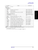


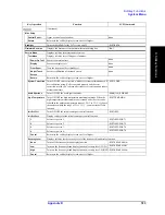


Appendix E
731
General Principles of Operation
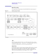
Data Processing
E. G
e
ne
ra
l Pr
in
ciple
s of
Op
er
ation
IF Range Correction
Input signals that went through ranging at the receiver are reverted (corrected) to previous
values before the ranging.
Ratio Calculation
The ratio between two signals is determined by performing divisions on complex numbers.
In the case of absolute measurements (Option 008), the ratio of complex number can not be
calculated.
Port Characteristics Correction
The equivalent source match error, the directivity error, and the tracking error of each test
port bridge are corrected. In the case of absolute measurements (Option 008), the gain of
each test port is corrected.
Sweep Averaging
The average of complex indices is determined based on data obtained from multiple sweep
measurements. Sweep averaging is effective in reducing random noise in measurements.
Raw Data Array
The results from all data processing done up to this point are stored in this array as raw
data. All prior data processing is performed as each sweep takes place. When the full
N-port error correction (N=2 to 4) is enabled, all 4
×
N S parameters are stored in the raw
data array and used in error correction. The user is not allowed to access (read/write) this
raw data array.
Error Correction/Calibration Coefficient Data Array
When error correction is enabled, the process eliminates the system errors that are
reproducible and stored in the calibration coefficient data array. It accommodates
everything from the simple vector normalization to the full 12-term error correction. The
user is allowed to access (read/write) this calibration coefficient data array.
Port Extension
This process carries out a simulation of adding or eliminating a variable length no-loss
transmission path on each test port so that the reference plane of calibration is moved. The
port extension is defined by an electrical delay (sec).
Fixture Simulator
A data conversion by the fixture simulator function is executed. The fixture simulator
function is a collective term for six different functions: balanced-unbalanced conversion,
addition of matching circuits, port reference impedance conversion, network elimination,
addition of differential matching circuits, and differential reference impedance conversion.
Summary of Contents for E5070B
Page 6: ......
Page 30: ...24 Contents ...
Page 34: ...28 Chapter1 Precautions Before contacting us ...
Page 286: ...280 Chapter6 Data Analysis Using the Equation Editor ...
Page 430: ...424 Chapter12 Optimizing Measurements Performing a Segment by Segment Sweep segment sweep ...
Page 538: ...532 Chapter15 Measurement Examples Executing Power Calibration ...
Page 634: ...628 AppendixB Troubleshooting Warning Message ...
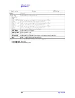
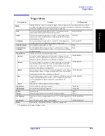
Page 732: ...726 AppendixD Softkey Functions Trigger Menu ...
Page 740: ...734 AppendixE General Principles of Operation Data Processing ...
Page 760: ...754 AppendixF Replacing the 8753ES with the E5070B E5071B Comparing Functions ...


