


330
Chapter 8
Frequency-Offset Measurement (Option 008)
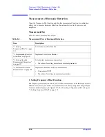
Measurement of Harmonic Distortion
Step 8.
Set
Segment Display
to
Freq Base
.
Step 9.
Press
Sweep Type
to select
Segment
.
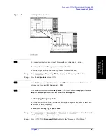
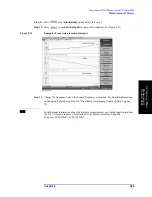
Step 10.
Press
to use Auto Scale All for trace scale optimization (Figure 8-15).
Figure 8-15
Example of Harmonic Distortion Measurement
NOTE
If you use the network analyzer as a tuning receiver like a spectrum analyzer, the setting
must be the same at both the frequency point at which the harmonic is generated and the
measurement point. Spectrum analyzers can detect all of the signals residing in the range of
sweep frequencies, but network analyzers can only detect the signals residing in the
measurement frequency point.
NOTE
For additional information about the absolute measurements, see Agilent application note
1463-6 “Accurate Frequency-Translating Device Measurements by using the
Frequency-Offset Mode, 5989-1420EN”.
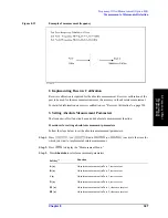
3 GHz
1 MHz
5
3.5 GHz
0 Hz
1
Table 8-5
Segment Table Settings
Center
Span
Point
Summary of Contents for E5070B
Page 6: ......
Page 30: ...24 Contents ...
Page 34: ...28 Chapter1 Precautions Before contacting us ...
Page 286: ...280 Chapter6 Data Analysis Using the Equation Editor ...
Page 430: ...424 Chapter12 Optimizing Measurements Performing a Segment by Segment Sweep segment sweep ...
Page 538: ...532 Chapter15 Measurement Examples Executing Power Calibration ...
Page 634: ...628 AppendixB Troubleshooting Warning Message ...
Page 732: ...726 AppendixD Softkey Functions Trigger Menu ...
Page 740: ...734 AppendixE General Principles of Operation Data Processing ...
Page 760: ...754 AppendixF Replacing the 8753ES with the E5070B E5071B Comparing Functions ...


