


336
Chapter 9
Analysis in Time Domain (Option 010)
Transformation to time domain
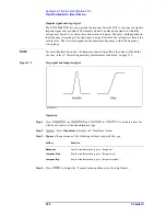
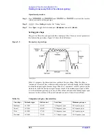
Impulse signal and step signal
The E5070B/E5071B lets you simulate the response from the DUT to two types of signals:
impulse signal and step signal. The impulse signal is a pulse-shape signal in which the
voltage rises from 0 to a certain value and returns to 0 again. The pulse width depends on
the frequency sweep range. The step signal is a signal in which the voltage rises from 0 to a
certain value. The rise time depends on the maximum frequency within the frequency
sweep range.
NOTE
For more information on how the frequency span setting affects the pulse width and the
rise time, refer to “Calculating necessary measurement conditions” on page 338.
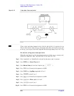
Figure 9-2
Step signal and impulse signal
Operation
Step 1.
Press
(or
) and
(or
) to activate a trace for
which you want to set the transformation type.
Step 2.
- Press
Transform
to display the “Transform” menu.
Step 3.
Type
and then press one of the following softkeys to specify the type.
Softkey
Function
Bandpass
Sets the transformation type to “band pass.”
Lowpass Step
Sets the transformation type to “lowpass step.”
Lowpass Imp.
Sets the transformation type to “lowpass impulse.”
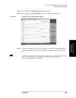
Step 4.
Press
to display the “Format” menu and then select the data format.
Summary of Contents for E5070B
Page 6: ......
Page 30: ...24 Contents ...
Page 34: ...28 Chapter1 Precautions Before contacting us ...
Page 286: ...280 Chapter6 Data Analysis Using the Equation Editor ...
Page 430: ...424 Chapter12 Optimizing Measurements Performing a Segment by Segment Sweep segment sweep ...
Page 538: ...532 Chapter15 Measurement Examples Executing Power Calibration ...
Page 634: ...628 AppendixB Troubleshooting Warning Message ...
Page 732: ...726 AppendixD Softkey Functions Trigger Menu ...
Page 740: ...734 AppendixE General Principles of Operation Data Processing ...
Page 760: ...754 AppendixF Replacing the 8753ES with the E5070B E5071B Comparing Functions ...


