


Chapter 10 Parameter
10.6 Servo Gain Adjustment
10-92
ME0392-4C
●
Adjustment of DC brush-less motor
No.
Problems
Adjustment method
1
•
Hunting occurs when
positioning stops
•
Speed irregularity occurs
during travel
•
Speed accuracy is
insufficient
Set the parameters following the procedure below and check the operation.
When the motion improves, end the adjustment. There is no
need to proceed to the next step.
Step 1: Change Driver Unit Parameter No. 32
“
Velocity Loop
Integral Gain
”
, set the following 5 values in order and
check the operation.
If the operation does not improve, perform step 2.
Setting order Velocity loop integral gain setting value
1
411
2
592
3
925
4
1,645
5
3,700
Step 2: Change Driver Unit Parameter No. 31
“
Velocity Loop
Proportional Gain
”
and Driver Unit Parameter No. 32
“
Velocity Loop Integral Gain"
Set the following 6 values in order and check the
operation.
● Load is 0.2 kg or less
Setting order
Velocity loop
proportional
gain setting value
Velocity loop
integral
gain setting value
1
42
382
2
42
520
3
42
749
4
42
1,171
5
42
2,081
6
42
4,683
If the operation does not improve, contact IAI.
● Load is heavier than
0.2 kg
Setting order
Velocity loop
proportional
gain setting value
Velocity loop
integral
gain setting value
1
32
231
2
32
315
3
32
453
4
32
708
5
32
1,259
6
32
2,833
2
Abnormal noise
In particular, high-pitched
noise occurs when stopping
or at low speed (20 mm/s or
less)
Change Driver Unit Parameter No. 31
“
Velocity Loop
Proportional Gain
”
and Driver Unit Parameter No. 32
“
Velocity
Loop Integral Gain
”
to the following values and confirm.
Velocity Loop Proportional Gain: 32
Velocity Loop Integral Gain: 231
10.7 Parameter Configuration (Advanced Use)
ME0392-4C
10-93
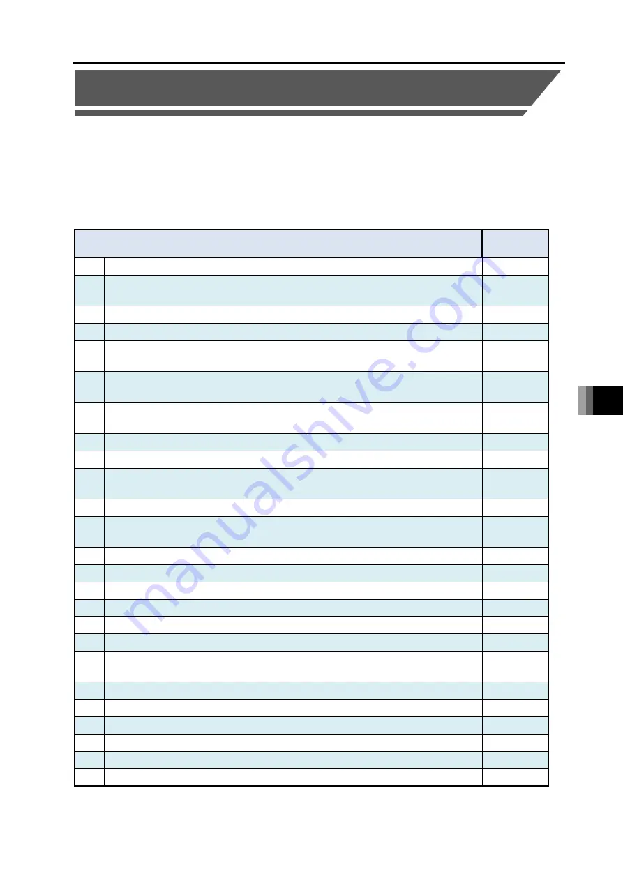
10.7 Parameter Configuration (Advanced Use)
Making a change to parameters should enable to add features and set dedicated features to the
input and output ports.
Shown below are some examples of setting in each operational conditions.
Make a change to the parameter settings on a table in the described pages when having a
required operation.
Make sure to read the applicable sections in the parameter list before proceeding to a change to
parameters.
Required Operation
Section to
Pick Up
1 Would like to have a temporary run without using I/O
10.7.1
2 Would like to have an output to judge activation of automatic operation from
RSEL controller
10.7.2
3 Would like to retain the current output status during an emergency stop
10.7.3
4 Would like to launch the emergency program
10.7.4
5 Would like to set up an automatic recovery (reboot) after an emergency stop is
canceled
10.7.5
6 Would like to set up an automatic recovery (error reset) after an emergency stop
is canceled
10.7.6
7 Would like to have a recovery from the status just before emergency stop was
made
10.7.7
8 Would like to have RSEL controller reset externally
10.7.8
9 Would like to have the servo turned on externally
10.7.9
10 Would like to have the home-return operation conducted externally on all the
single-axis actuators
10.7.10
11 Would like to have a program in RSEL controller activated externally
10.7.11
12 Would like to have a program activated externally by conducting a command in a
program number in binary
10.7.12
13 Would like to have the RSEL controller paused externally
10.7.13
14 Would like to have an error reset conducted externally
10.7.14
15 Would like to release the brake on an actuator externally
10.7.15
16 Would like to toggle AUTO Mode and MANU Mode externally
10.6.16
17 Would like to have the input port assignment changed
10.7.17
18 Would like to output that all the single-axis actuators are at the home positions
10.7.18
19 Would like to output that all the single-axis actuators has completed the home
return operation
10.7.19
20 Would like to output that a single-axis actuator has got in the set area (zone)
10.7.20
21 Would like to output an error level
10.7.21
22 Would like to output that an actuator is in an emergency stop
10.7.22
23 Would like to know the current operation mode
10.7.23
24 Would like to have the output port assignment changed
10.7.24
25 Would like to use SIO connection connectors
10.7.25
Содержание R-unit RSEL
Страница 2: ......
Страница 5: ...ME0392 4C 2 Quick Start Guide Japanese Only ...
Страница 32: ...Actuator Coordinate System Intro 18 ME0392 4C 2 Slider type 3 Table type 0 0 0 0 ...
Страница 50: ...Chapter 1 RSEL System 1 4 Installation 1 13 ME0392 4C ...
Страница 82: ...Chapter 2 System Configuration and Power Specifications 2 6 Drive Source Cutoff 2 30 ME0392 4C ...
Страница 244: ...Chapter 4 Unit connection Installation and Wiring 4 5 PIO Circuit 4 32 ME0392 4C ...
Страница 249: ...Chapter 4 Unit connection Installation and Wiring 4 7 Brake Box Option ME0392 4C 4 37 Appearance ...
Страница 251: ...Chapter 4 Unit connection Installation and Wiring 4 7 Brake Box Option ME0392 4C 4 39 Appearance ...
Страница 316: ...Chapter 5 Operation 5 10 ELECYLINDER Operation 5 52 ME0392 4C ...
Страница 438: ...Chapter 6 Field Network PIO SIO 6 5 Example of Connectivity Setting 6 120 ME0392 4C ...
Страница 472: ...Chapter 7 6 axis Cartesian Robot 7 2 Caution When Using Orthogonal Coordinate System Features 7 33 ME0392 4C ...
Страница 530: ...Chapter 9 Special Functions 9 6 RSEL Serial Communication Multiple Channel Applicable Features 9 38 ME0392 4C ...
Страница 532: ...10 6 Servo Gain Adjustment 10 90 10 7 Parameter Configuration Advanced Use 10 93 ...
Страница 638: ...Chapter 10 Parameter 10 7 Parameter Configuration Advanced Use 10 106 ME0392 4C ...
Страница 838: ...Chapter 14 Warranty 14 Warranty 14 3 ME0392 4C ...
Страница 843: ......
Страница 844: ......