


Chapter 5 Operation
5.3
Axis Setting
5-10
ME0392-4C
[2] Logical axis area
The assigned axis image is displayed in the logical axis area.
Eight axis slots are always displayed (Axis1 to Axis8), and “Not assigned” is displayed for slots
with no axis assigned.
Figure 5.3-6 Axis setting status
Axis images can be moved within the logical axis area.
Note, however, that there are restrictions on the logical axis order for special mechanism axes,
so movement of the axes may be restricted.
Example :
The message in the red dotted frame in Figure 5.3-6 is an error message that appears when
trying to assign the axis image of Axis5 to Axis3.
5.3
Axis Setting
ME0392-4C
5-11
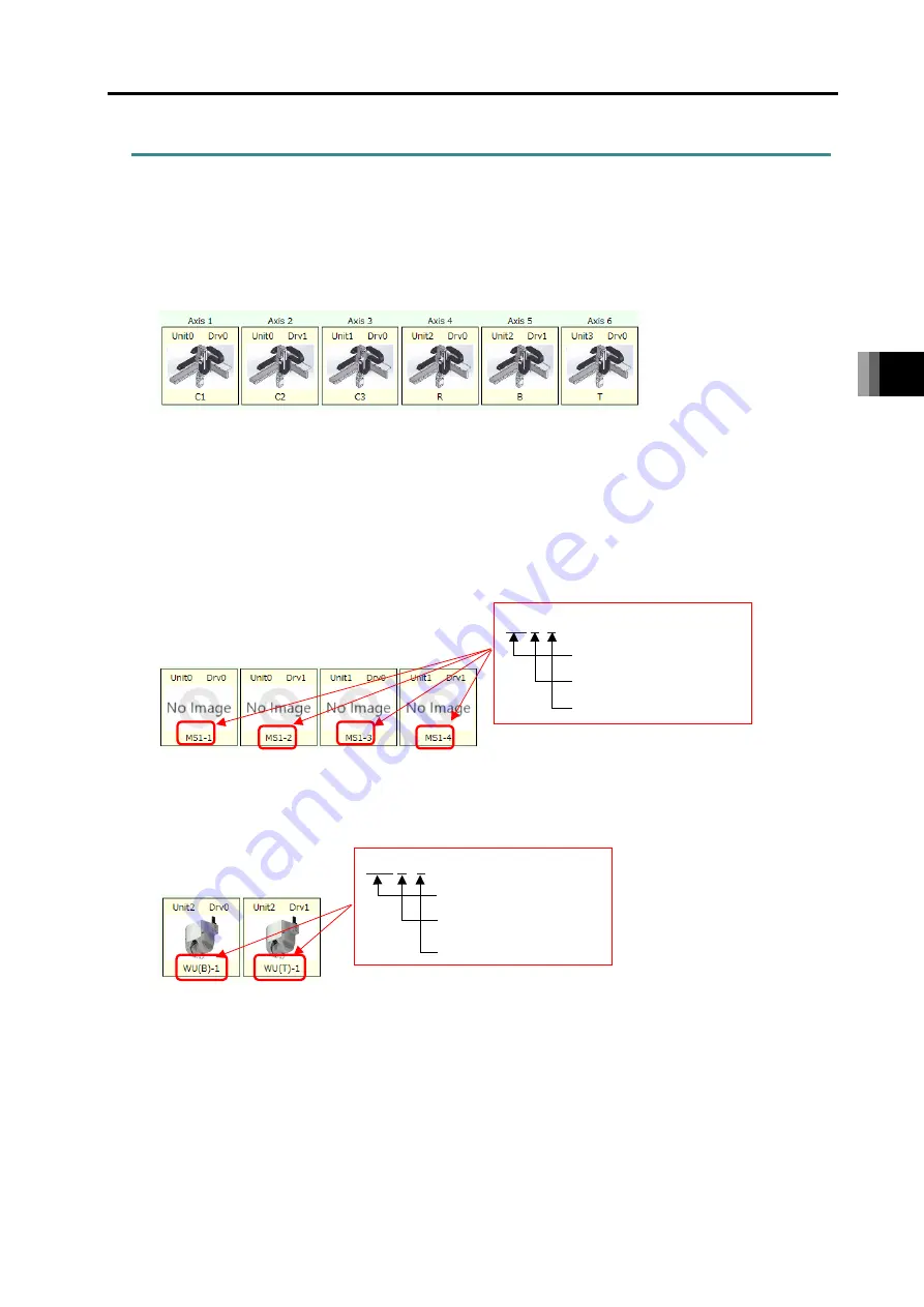
5.3.5 Special mechanism axis
A special mechanism axis is a general term for axes that have a special mechanism as a function
of an actuator.
There are the following three types of special mechanism axes.
(1) 6-axis Cartesian Robot
There are some restrictions as shown below when a 6-axis Cartesian robot is connected.
• Regardless of the order of driver units mounted, the logic axis numbers should be fixed.
• It is not available to assign or cancel axes (transfer between physical axis area and logical
axis area)
• The actuator names should be C1, C2, C3, R, B and T.
• The figures of actuators are those of the 6-axis cartesian robot.
(2) Multi slider axis
When dragging and dropping the multi-slider axis from the physical axis area to the logical
axis area, the axes to be paired (in the above case, MS1-1 to MS1-4) also move.
(3) Wrist unit
When dragging and dropping the wrist unit from the physical axis area to the logical axis area,
the axes that are paired also move together. Also, in the logical axis area, the B axis must be
assigned to a logical axis number that is always lower than the T axis.
MS
○
-×
Multi-slider abbreviation
Combination number
Slider number
WU (
○
)
-
×
Wrist unit
abbreviation
B
:
B
axis,
T
:
T
axis
Combination number
Содержание R-unit RSEL
Страница 2: ......
Страница 5: ...ME0392 4C 2 Quick Start Guide Japanese Only ...
Страница 32: ...Actuator Coordinate System Intro 18 ME0392 4C 2 Slider type 3 Table type 0 0 0 0 ...
Страница 50: ...Chapter 1 RSEL System 1 4 Installation 1 13 ME0392 4C ...
Страница 82: ...Chapter 2 System Configuration and Power Specifications 2 6 Drive Source Cutoff 2 30 ME0392 4C ...
Страница 244: ...Chapter 4 Unit connection Installation and Wiring 4 5 PIO Circuit 4 32 ME0392 4C ...
Страница 249: ...Chapter 4 Unit connection Installation and Wiring 4 7 Brake Box Option ME0392 4C 4 37 Appearance ...
Страница 251: ...Chapter 4 Unit connection Installation and Wiring 4 7 Brake Box Option ME0392 4C 4 39 Appearance ...
Страница 316: ...Chapter 5 Operation 5 10 ELECYLINDER Operation 5 52 ME0392 4C ...
Страница 438: ...Chapter 6 Field Network PIO SIO 6 5 Example of Connectivity Setting 6 120 ME0392 4C ...
Страница 472: ...Chapter 7 6 axis Cartesian Robot 7 2 Caution When Using Orthogonal Coordinate System Features 7 33 ME0392 4C ...
Страница 530: ...Chapter 9 Special Functions 9 6 RSEL Serial Communication Multiple Channel Applicable Features 9 38 ME0392 4C ...
Страница 532: ...10 6 Servo Gain Adjustment 10 90 10 7 Parameter Configuration Advanced Use 10 93 ...
Страница 638: ...Chapter 10 Parameter 10 7 Parameter Configuration Advanced Use 10 106 ME0392 4C ...
Страница 838: ...Chapter 14 Warranty 14 Warranty 14 3 ME0392 4C ...
Страница 843: ......
Страница 844: ......