


Chapter 3 Specifications for each unit
3.6
EC Connection Unit
3-108
ME0392-4C
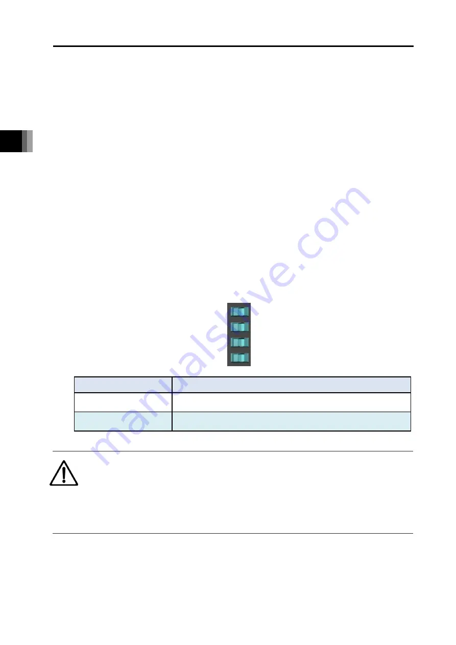
(3) Jog switch
They are switches for the jog operation. It comes the switches for 1st, 2nd, 3rd and 4th axes
from the top.
Set a switch to the JOG+ side and the jog operation to the positive direction (target position
registered as the forward end in the position data) should be made and set it to the JOG- side
and the jog operation to the negative side (target position registered as the backward end) to
be made. The jog speed should be the velocity registered in the position data. If the switch
gets released on the way, stop should be performed with the deceleration registered in the
position data. However, if the home-return operation is incomplete, it should perform the
home-return operation no matter which side the switch is set to. Releasing the switch one the
way should cancel the home-return operation.
The operation on on the jog switch is valid only in MANU Mode. It should be invalid in AUTO
Mode. Also, when a window to operate actuators is open on a teaching tool, the jog switch
should be inactivated. If a window capable to operate actuators gets opened during operation
with the jog switch, an actuator should decelerate and stop.
Setting “EC Connection Unit JOG Switch” I/O Parameter No.191 in “1: invalid” should make
the jog switches on all the units of the EC connection unit connected to the SEL unit
inactivated. (It is set to “Valid” in the initial setting.)
Symbol
Description
JOG+
Jog operation to positive direction (target position registered as
forward end in position data)
JOG-
Jog operation to negative direction (target position registered as
backward end in position data)
Caution
The jog switch is disabled when the communication with the teaching tool is
disconnected while the screen in which the actuator can be operated with the teaching
tool is opened.
To enable jog switch operation again, turn the REC system on again or perform
software reset.
JOG-
JOG+
Содержание R-unit RSEL
Страница 2: ......
Страница 5: ...ME0392 4C 2 Quick Start Guide Japanese Only ...
Страница 32: ...Actuator Coordinate System Intro 18 ME0392 4C 2 Slider type 3 Table type 0 0 0 0 ...
Страница 50: ...Chapter 1 RSEL System 1 4 Installation 1 13 ME0392 4C ...
Страница 82: ...Chapter 2 System Configuration and Power Specifications 2 6 Drive Source Cutoff 2 30 ME0392 4C ...
Страница 244: ...Chapter 4 Unit connection Installation and Wiring 4 5 PIO Circuit 4 32 ME0392 4C ...
Страница 249: ...Chapter 4 Unit connection Installation and Wiring 4 7 Brake Box Option ME0392 4C 4 37 Appearance ...
Страница 251: ...Chapter 4 Unit connection Installation and Wiring 4 7 Brake Box Option ME0392 4C 4 39 Appearance ...
Страница 316: ...Chapter 5 Operation 5 10 ELECYLINDER Operation 5 52 ME0392 4C ...
Страница 438: ...Chapter 6 Field Network PIO SIO 6 5 Example of Connectivity Setting 6 120 ME0392 4C ...
Страница 472: ...Chapter 7 6 axis Cartesian Robot 7 2 Caution When Using Orthogonal Coordinate System Features 7 33 ME0392 4C ...
Страница 530: ...Chapter 9 Special Functions 9 6 RSEL Serial Communication Multiple Channel Applicable Features 9 38 ME0392 4C ...
Страница 532: ...10 6 Servo Gain Adjustment 10 90 10 7 Parameter Configuration Advanced Use 10 93 ...
Страница 638: ...Chapter 10 Parameter 10 7 Parameter Configuration Advanced Use 10 106 ME0392 4C ...
Страница 838: ...Chapter 14 Warranty 14 Warranty 14 3 ME0392 4C ...
Страница 843: ......
Страница 844: ......