Restrictions on creepless operation
(1) The acceleration commanded during a creepless operation will not exceed the specified
acceleration.
(2) Do not change the reference speed (pre-ramp) during a creepless operation.
(3) After the end of running (including the end of operation due to the protective function triggered
and a coast-to-run command received), turn the
CRPLS
command OFF.
(4) In any of the following cases, the creepless operation is forcedly terminated.
- Such a speed pattern that the speed does not reach 0 after the elevator cage moves the
specified moving distance.
- Reference speed (pre-ramp) is nonzero.
- Run command is OFF.
After the forced termination, the inverter continues to run with the speed control not involving a
creepless operation. No protective function (trip) works. No further creepless operation takes
place until the inverter stops.
Input timing of a creepless operation command
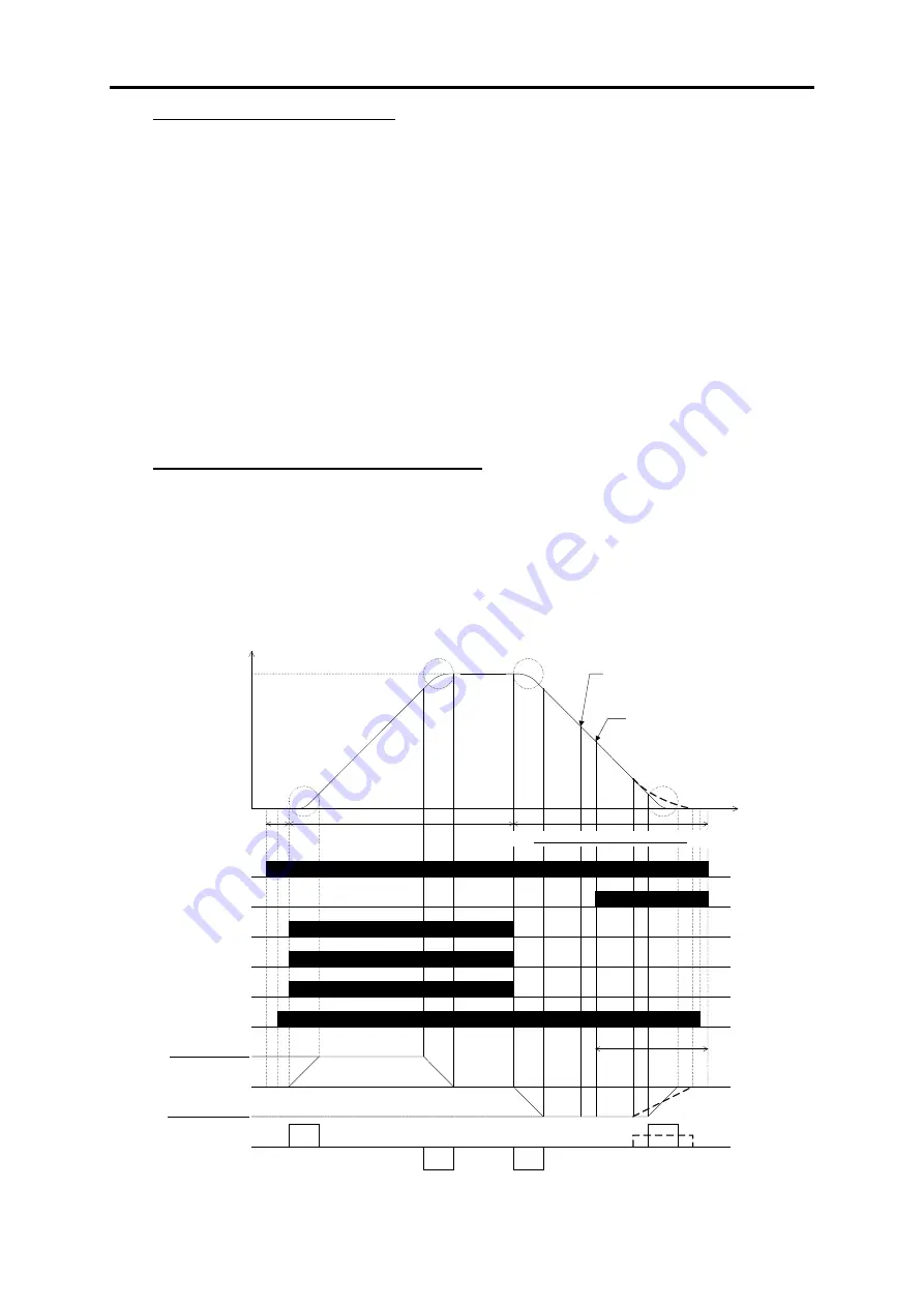
The graph below shows a basic pattern of a creepless operation using the "Start creepless operation"
command
CRPLS
. The
CRPLS
command should be given within zone "A" ranging from the end to
the start of deceleration.
The following example shows deceleration from high speed to zero speed. The waveforms drawn
with broken lines show the speed, acceleration and jerk applied when the
CRPLS
command is given
earlier than the ones drawn with full lines.
High speed
Speed
Time
Zero speed
ON
FWD
SS1
SS2
ON
ON
SS4
ON
Zero speed
command
High speed
command
CRPLS
ON
Release
Acceleration
Jerk
Theoretical starting point of
creepless operation
Practical starting point of
creepless operation
Creepless operation
Zone A: Zero speed command
L24: S-curve
setting 6
L25: S-curve
setting 7
E12: Acceleration/
deceleration time 5
E13: Acceleration/deceleration time 6
L28: S-curve setting 10
L19: S-curve setting 1
Brake
Maximum speed
Acceleration time
Maximum speed
Deceleration time
(Calculated by arrival point and moving
distance)
Example of Creepless Operation with
CRPLS
2-150
Содержание Frenic lift
Страница 1: ...LM2A series Reference Manual INR SI47 1909a E...
Страница 7: ......
Страница 13: ......
Страница 51: ...2 38...
Страница 221: ......
Страница 242: ...3 4 Programming Mode Chap 3 OPERATION USING TP A1 LM2 Figure 3 14 Screen transition for Op Monitor display example 3 21...
Страница 252: ......
Страница 254: ...URL http www fujielectric com...


