FWD
REV
ON
ON
t
Speed detected
(rpm)
ON
ON
ON
ON
ON
ON
t
L111
TDCP
TDCL
ON
ON
L112 (%)
ON
ON
EN1&EN2
ON
ON
ON
ON
ON
ON
ON
ON
Alarm (tCA)
ON
L113=0
L113=0
L113=1
L113=1
L113=2
L113=3
Light alarm (tCW)
ON
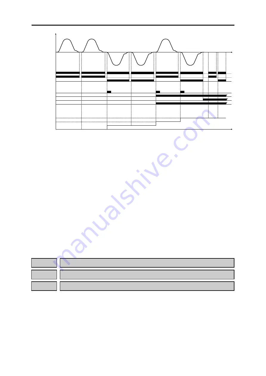
Figure 1. Basic function time chart of TDC function
■
Travel direction counter (Total number of direction changes) (L114)
This is READ ONLY function code. It shows the total number of direction changes. When running
direction is changed from
FWD
to
REV
or from
REV
to
FWD
this counter is increased. This
parameter cannot be modified in order to detect if TDC function is used propertly. In other words, if
total number of direction changes, direction changes limit and total number of resets doesn’t match,
it means that somebody is manipulating intentionally the inverter in order to avoid changing
suspension means. Therefore, by means of this counter, sabotage can be detected.
Monitoring range is from 0.01~10.00 Million direction changes, where
0.01 means 10.000 changes
and 10.00 means 10.000.000 changes.
■
Travel direction counter (Total number of resets) (L115)
This is READ ONLY function code. It shows the total number of reset operations. This counter
increments one unit each time that parameter L113 is modified.
For additional information about TDC function, refer to related Application Note
(AN-Lift2-0004v100EN).
L117
Rescue operation by brake control (Speed limit)
L118
Rescue operation by brake control (Apply time)
L119
Rescue operation by brake control (Speed detection delay time)
When there is a blackout, one possible solution to rescue trapped people in lift car is to perform a
rescue operation by brake control. In this case, inverter will control motor’s brake (opening and
closing) in order to move the lift by load unbalance (by gravity).
This solution is very useful in case of gearless motors (both synchronous and asynchronous). As
gearless motors has no gear box, the system becomes more reversible. Also, it is very useful in case
of MRL installations (Machine Room less) where reaching the brake is not easy.
Rescue operation by brake control will move lift car by gravity. In order to keep a safety operation,
inverter will monitor lift speed under this operation. This function is not available under Torque
Vector Control as motor speed cannot be monitored.
2-184
Содержание Frenic lift
Страница 1: ...LM2A series Reference Manual INR SI47 1909a E...
Страница 7: ......
Страница 13: ......
Страница 51: ...2 38...
Страница 221: ......
Страница 242: ...3 4 Programming Mode Chap 3 OPERATION USING TP A1 LM2 Figure 3 14 Screen transition for Op Monitor display example 3 21...
Страница 252: ......
Страница 254: ...URL http www fujielectric com...


