2.3 Overview of Function Code
C
hap.
2
FUN
CT
IO
N
C
O
D
E
S
■
Stop bit selection (y07, y17)
Sets the stop bit.
•
For inverter supporting loader (via RS-485):
The value does not need to be set since it
automatically becomes 1 bit.
For Modbus RTU: The value does not need to be set
since it is automatically determined in conjunction
with the parity bit (function y06, y16).
y07 and y17 data
Function
0
2 bits
1
1 bit
■
Communication time-out detection timer (y08, y18)
When the operation commands are given using the
RS-485 communication, this parameter sets the time
to detect a communication time-out (for any reason
such as disconnection from the host equipment that
is periodically accessing to the inverter). The time is
counted from the last valid data received.
For details on processing communication errors,
refer to y02 and y12.
y08 and y18 data
Function
0
Disconnection is not
detected.
1 to 60
Detection time from 1 to
60 (s)
■
Response interval time (y09, y19)
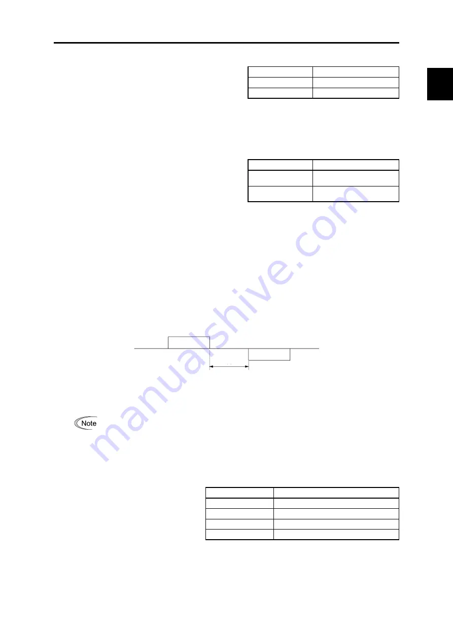
Sets a period from the time when the system receives a request from host equipment (upper
equipment such as computer or PLC) until the time when it returns a response. In case of the host
equipments that are slow to process the task from completed transmission to completed reception
preparation, a timing can be synchronized by setting the response interval time.
-Data setting range: 0.00 to 1.00 (s)
T1 = Response interval time + α
α: Processing time
inside the inverter. It varies depending on the timing and command.
For details, refer to the RS-485 Communication User’s Manual.
To set an inverter by the inverter supporting loader via the RS-485 communication,
consider the performance and condition of the computer and converter (such as
USB-RS-485 converter).
(Some converters monitor communication status and switch transmission and reception
with timer.)
■
Protocol selection (y10, y20)
Selects a communication protocol.
y10 and y20 data
Function
0
Modbus RTU protocol
1
FRENIC Loader protocol
2
Reserved for particular manufacturers
5
DCP protocol
Host device
Request
Inverter
Response
T1
2-135
Содержание Frenic lift
Страница 1: ...LM2A series Reference Manual INR SI47 1909a E...
Страница 7: ......
Страница 13: ......
Страница 51: ...2 38...
Страница 221: ......
Страница 242: ...3 4 Programming Mode Chap 3 OPERATION USING TP A1 LM2 Figure 3 14 Screen transition for Op Monitor display example 3 21...
Страница 252: ......
Страница 254: ...URL http www fujielectric com...


