


install - concepts - PixMaster - switcher - CG - clips - controls - team - appendix
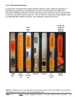
FLINT
V1.1
1.5
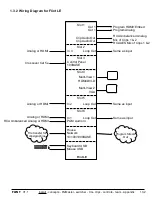
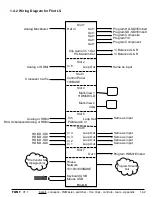
1.5 Optional Tally Box
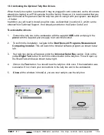
There are 2 tally box options for Flint Systems to provide a contact closure/relay connection.
The tally boxes are stand-alone: Sense & Switch 8 and a Measurement Computing USB-
ERB24 that plug into the Server via a USB connection. Up to 11 external tally/GPIO boxes may
be connected along with the built in tally/GPO on the Flint Switcher for a maximum 96 GPIs
and 288 GPOs.
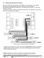
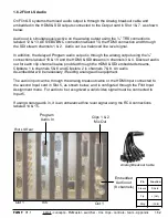
The Sense & Switch 8 provides 8 relays for tally output to your camera control units and 8
isolated inputs for General Purpose Inputs contact points for triggering Macros. All 6 external
sources plugged into the Flint Input boards can be tallied, as shown by the diagram below.
Connectors 6 & 7 on the Tally Box may be used for GPOs to trigger external devices.
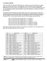
Input 1 on the Flint card corresponds to ‘0’ on Tally Box
Input 2 on the Flint card corresponds to ‘1’ on Tally Box
Input 3 on the Flint card corresponds to ‘2’ on Tally Box
Input 4 on the Flint card corresponds to ‘3’ on Tally Box (LS Only)
Input 5 on the Flint card corresponds to ‘4’ on Tally Box (LS Only)
Input 6 on the Flint card corresponds to ‘5’ on Tally Box (LS Only)
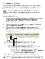
Each relay contact is rated at 6 amps at 120 volts AC or 28 volts DC. The convenient screw
terminals can accept cable from 12 to 22 AWG.
NOTE:
The ‘Inputs Contacts’ (IP A/B) are for General Purpose Inputs (GPI). The ‘Relay Contacts’ are for
Tally. ‘NO’ for Normally Open, ‘C’ for Common or Ground, ‘NC’ for Normally Closed.


