8-6 Application
BE1-CDS220
87
Mode1
87RT
87RPU
IN4 Not Used
OPTO
IN3 86 Status
OPTO
IN2 Breaker2 Status
OPTO
IN1 Breaker1 Status
OPTO
D2843-23.vsd
09-23-99
ACTIVE
SETTING
GROUP
CONTROL
Mode1
SG0
SG2
SG1
SG3
BLK
AUTO
D3
D2
D1
D0
5
Note: For clarity, multiple variables going to
the same OR Gate are shown by a single line
into the OR Gate.
87UT
2NDHAR
5THHAR
51P
Mode1
51PT
51PPU
51N
Mode1
51NT
51NPU
51Q
Mode1
51QT
51QPU
BLK
BLK
BLK
5
VO11 PROT TRIP
VO12 PROT PU
VOA
Relay
Trouble
OUTA
Output
Logic
VO1
87 Trip
OUT1
Output
Logic
VO2
87 Trip
OUT2
Output
Logic
Alarm
ALMMAJ
ALMMIN
ALMLGC
SA-
RESET
VO6
Major Alarm
Output
Logic
IN5 Not Used
OPTO
OPTO
IN6 Alarm
OPTO
IN8 Alarm
OPTO
VO13 Alarm Point 21
VO15 Alarm Point 23
IN7 Alarm
VO14 Alarm Point 22
VO3
87 Trip
OUT3
Output
Logic
VO4
51 Trip
OUT4
Output
Logic
OUT5
Output
Logic
VO5
Not Used
3
OUT6
0
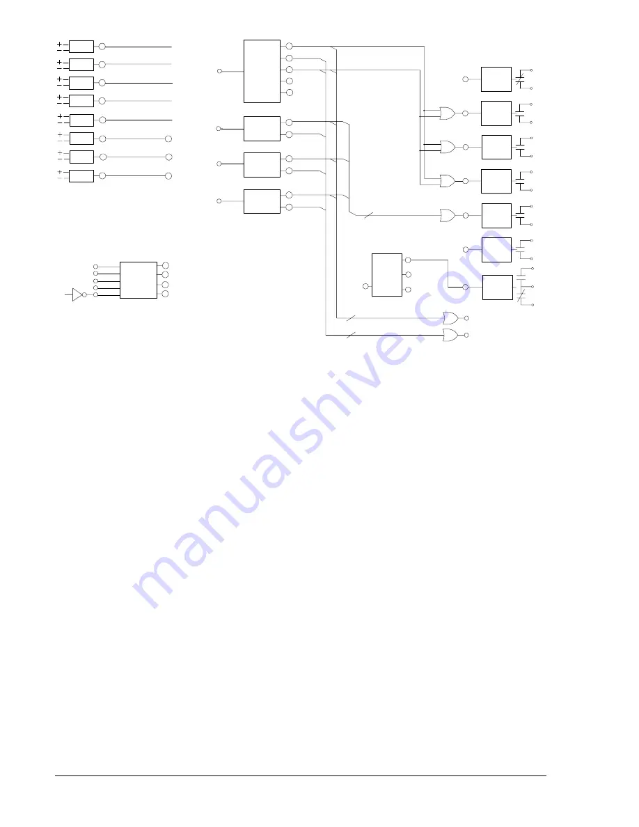
Figure 8-2. Typical Logic Diagram for BASIC-87
Protection Elements
Referring to all four schemes (Generator, Motor, Bus, and Transformer) in Figure 8-1, the 87 protection
element is connected to CT input 1 and CT input 2. The 51 protection element is also connected to the CT
input 1. The 87 and 51 protection elements are logic enabled by the programming shown in Table 8-1 to
provide a trip through the BE1-CDS220 output contacts.
Typically, the 87 protection element provides high-speed percent restrained, phase, and ground protection
for faults inside the differential zone. For the generator, motor, and bus applications shown in Figure 8-1,
the percent-restrained differential protection function is the only function of the 87 protection element
required. Set the pickup of the 2
nd
, 5
th
, and 87 unrestrained functions to 0 (setting disabled). The 87
restrained function has a setting when the 2
nd
and 5
th
harmonic restraint functions are set for the
transformer application shown in Figure 8-1 (refer to the discussion in Overview of Preprogrammed Logic
Schemes).
Typically, the 51 protection element is coordinated with down-line protection devices to provide
overlapping Phase, Neutral, and Negative Sequence timed backup protection for zones beyond the
equipment being protected. In the low impedance, bus application, the 51 protection element must
coordinate with the feeder protection of the circuits connected to the bus.
Integration of Protection, Control, and I/O Elements
The logic settings in Table 8-1 also include the logic equations that connect the various elements of the
basic differential scheme. For example, the three underlined commands in the equations of Table 8-1
provide the electrical connection between the 87 element (trip enabled by the settings) and trip outputs 1,
2, and 3. Referring to Figures 8-1 and 8-2, the 87 protection element trips through outputs 1, 2, and 3. The
user can apply any or all of the outputs. The 51 protection element (also trip enabled by the settings) trips
through output 4. There are no virtual switches used in this application.
Control of the active setting group can be manual or automatic. For the BASIC-87 application, setting
group control is programmed for continuous automatic operation because the /0 (not 0), logic 1 is applied
to the AUTO input of the Active Setting Group Control Logic as shown in Figure 8-2.
Содержание BE1-CDS220
Страница 2: ......
Страница 10: ...viii Introduction BE1 CDS220 This page intentionally left blank...
Страница 36: ...ii Quick Start BE1 CDS220 This page intentionally left blank...
Страница 48: ...ii Input And Output Functions BE1 CDS220 This page intentionally left blank...
Страница 66: ...iv Protection and Control BE1 CDS220 This page intentionally left blank...
Страница 112: ...ii Metering BE1 CDS220 This page intentionally left blank...
Страница 116: ...5 4 Metering BE1 CDS220 This page intentionally left blank...
Страница 166: ...ii BESTlogic Programmable Logic BE1 CDS220 This page intentionally left blank...
Страница 176: ...7 10 BESTlogic Programmable Logic BE1 CDS220 This page intentionally left blank...
Страница 234: ...8 56 Application BE1 CDS220 This page intentionally left blank...
Страница 236: ...ii Security BE1 CDS220 This page intentionally left blank...
Страница 240: ...9 4 Security BE1 CDS220 This page intentionally left blank...
Страница 242: ...ii Human Machine Interface BE1 CDS220 This page intentionally left blank...
Страница 256: ...10 14 Human Machine Interface BE1 CDS220 This page intentionally left blank...
Страница 258: ...ii ASCII Command Interface BE1 CDS220 This page intentionally left blank...
Страница 289: ...BE1 CDS220 Installation 12 7 Figure 12 8 MX Case Horizontal Panel Mount Front View Overall Dimensions...
Страница 422: ...14 32 BESTCOMS Software BE1 CDS220 This page intentionally left blank...
Страница 424: ...ii Time Current Characteristics BE1 CDS220 This page intentionally left blank...
Страница 441: ...BE1 CDS220 Time Overcurrent Characteristic Curves A 17 Figure A 13 Time Characteristic Curve A Standard Inverse 99 1621...
Страница 442: ...A 18 Time Overcurrent Characteristic Curves BE1 CDS220 Figure A 14 Time Characteristic Curve B Very Inverse 99 1376...
Страница 443: ...BE1 CDS220 Time Overcurrent Characteristic Curves A 19 Figure A 15 Time Characteristic Curve C Extremely Inverse 99 1377...
Страница 444: ...A 20 Time Overcurrent Characteristic Curves BE1 CDS220 Figure A 16 Time Characteristic Curve G Long Time Inverse 99 1622...
Страница 452: ...ii Terminal Communication BE1 CDS220 This page intentionally left blank...
Страница 456: ...C 4 Terminal Communication BE1 CDS220 This page intentionally left blank...
Страница 458: ...ii Settings Calculations BE1 CDS220 This page intentionally left blank...
Страница 475: ......


