2:
El
em
en
t w
ith
Po
w
er
S
ta
tio
n:
S
et
up
an
d
C
on
ne
ct
io
ns
•
14
©2016 Axia Audio- Rev 1.8.1
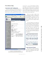
PowerStation - Rear Panel
As you can see in Figure 2-3, there are no switches
or controls on the PowerStation rear panel. All setup is
performed with software. The rear panel consists of only
connectors and indicators.
Power
There are two power connectors on the PowerSta-
tion. PSU1 (MAIN) is the standard IEC receptacle for
your mains power. This is auto-sensing for voltages in
the range from 100 to 240 VAC.
The second power supply connection is labelled
PSU2 (BACKUP). It is to be used only in conjunction
with a PowerStation AUX chassis. This is a type 7W2
DB-combo connector to be used exclusively for this
purpose. If there is a failure of either the PowerStation
MAIN or AUX’s power supply, it will automatically uti-
lize backup power provided by this connector and the
PSU indicator on the front panel will indicate the failure
condition.
Note: The PowerStation MAIN and AUX provide
backup power to each other. The failure of a
power supply in either a MAIN or AUX unit will
cause it to automatically and seamlessly use the
backup power supplied by the remaining healthy
unit.
Do not connect the PSU2 connector to any device
other than a PowerStation MAIN or AUX chassis. If you
are connecting an AUX to a “hot” MAIN, be sure the
AUX unit is powered up by first connecting PSU1 to
your mains power supply.
Audio Connections
The PowerStation’s rear panel contains all of the
connectors used for audio I/O, Ethernet, GPIO, power
supply and the connections to your Element control sur-
face. Note that we use RJ-45 connectors are used for four
purposes:
• Analog audio inputs and outputs
• AES audio inputs and outputs
• CANBus (Element internal modules and exter-
nal accessory panels)
• Ethernet (some with PoE - Power over Ethernet)
It is important to follow the proper conventions for
wiring these connectors and ensure that the connector
functions are not confused as some damage may result
with improper connections.
Analog and AES Audio
The connector pin functions shown in Figure 2-4 are
the same for both the AES and Analog inputs and out-
puts.
Figure 2-3: PowerStation MAIN Rear Panel Connections
Содержание element v.2.0
Страница 100: ...5 Element Operations 90 2016 Axia Audio Rev 1 8 1 Capital budget may you never decrease for we need new test gear...
Страница 149: ...Appendix A Specifications 139 2016 Axia Audio Rev 1 8 1...
Страница 183: ...Warranty 173 2016 Axia Audio Rev 1 8 1 TCP IP How did we live without thee Analogicly...
Страница 184: ...THIS PAGE INTENTIONALLY LEFT BLANK...
Страница 185: ...THIS PAGE INTENTIONALLY LEFT BLANK...


