2: E
le
m
en
t w
ith
Po
w
er
S
ta
tio
n: S
et
up
an
d
C
on
ne
ct
io
ns
•
1
2
©2016 Axia Audio- Rev 1.8.1
The Basics
If you are using a single PowerStation with an Ele-
ment control surface, there is not too much planning re-
quired since the factory default configuration is designed
for out-of-box stand-alone operation. If, however, you
plan to interconnect your new PowerStation with other
Livewire gear in a larger network, you will need to be
organized. This is no different than any other studio
project. Lets have a peek under the hood and see what
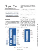
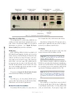
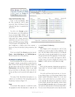
the PowerStation can do. Figure 2-1 illustrates the build-
ing blocks of the PowerStation MAIN and PowerStation
AUX.
The PowerStation inputs are the sources in your
studio such as microphones, cd players and other audio
playback devices The audio outputs of the PowerSta-
tion will be connected to control room monitors, preview
(cue) speaker, headphones amplifiers and possibly some
audio recording devices. These external audio devices
may be analog or AES devices as shown in Figure 2-1.
The GPIO ports are used for control interfaces with
other external devices such as air lights, recorders and
CD players,
The 100 Mbps Ethernet ports may be used to connect
PCs running Axia’s IP-Audio driver or expand your sys-
tem by adding other Livewire devices such as Axia 8x8
nodes or a PowerStation AUX.
The 1000 Mbps Ethernet ports are used to connect to
your PowerStation to other PowerStation MAIN units or
an Ethernet core switch.
The remaining connectors are used to connect your
control surface and its DVI-D monitor.
Getting Prepared
Before you dive into the hardware, you’ll need to de-
termine a range of IP addresses to assign to each studio
and log each device’s IP as you assign it; Appendix F
contains an IP Assignment Worksheet you can use for
this purpose. IP addresses used in an Axia network must
be valid Unicast IP addresses. Determine your network’s
subnet mask settings at the same time (typically this val-
ue is set at 255.255.255.0 for intranet applications).
A PowerStation MAIN with a PowerStation AUX
will require a range of four consecutive IP addresses.
You will specify the first of these addresses and the oth-
ers will be assigned automatically - be sure to accom-
modate these four consecutive addresses in your IP plan.
Unicast vs. Multicast IP Addresses: Data
is routed over IP networks in one of two ways:
point-to-point unicast or multicast.
Livewire devices use common TCP/IP unicast IP
addresses for control and web browser access.
These are numbers you assign within the range
used by your network. Since most Livewire
networks are not intended to be accessed via
the Internet, we recommend you use the non-
routable IP addresses such as the range of
192.168.0.0 to 192.168.255.255. These IP ad-
dresses have been set aside specifically for use
with local networks.
Multicast allows efficient one-to-many connec-
tions, so Livewire uses that for its audio streams,
source advertising, and synchronization signals.
You do not need to assign these multicast ad-
dresses because the system does this automati-
cally.
For more information on network construction,
please refer to our companion Introduction to
Livewire: System Design Reference and Primer
available at
https://www.telosalliance.com/Axia
.
When you install the PowerStation, please mount it
in an equipment rack that has free air flow. DO NOT ob-
struct the air flow to the PowerStation since it is depen-
dent on convection cooling. The PowerStation does not
have any fans so you can use it in a quiet studio environ-
ment but you MUST provide adequate ventilation. Do
not obstruct the air flow above or below the PowerSta-
tion. Those vents serve a very important purpose.
To install the Element control surface in your studio
furniture, you’ll need to prepare a cutout in the counter
top. A dimensional drawing with all pertinent measure-
ments is found in Appendix A: Specifications. Make
certain that there’s adequate clearance inside the furni-
ture for the required power cable entry into the console;
knockout plugs are located at both bottom rear corners of
Element for cable routing access.
Содержание element v.2.0
Страница 100: ...5 Element Operations 90 2016 Axia Audio Rev 1 8 1 Capital budget may you never decrease for we need new test gear...
Страница 149: ...Appendix A Specifications 139 2016 Axia Audio Rev 1 8 1...
Страница 183: ...Warranty 173 2016 Axia Audio Rev 1 8 1 TCP IP How did we live without thee Analogicly...
Страница 184: ...THIS PAGE INTENTIONALLY LEFT BLANK...
Страница 185: ...THIS PAGE INTENTIONALLY LEFT BLANK...


