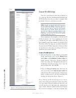
3: C
on
fig
uri
ng I
np
ut
s •
38
©2016 Axia Audio- Rev 1.8.1
Let’s say you’ve connected a hybrid to your Ana-
log Node, named it “Studio 1 Phone”, and assigned it a
channel number of 12205. You’ve constructed a Source
Profile for it, and you now want to give it a mix-minus
backfeed and set up a GPIO contact closure for the “take”
and “drop” functions. Here’s how:
1. Make sure that, in your hybrid’s Source Profile, the
Source Type
option is set to “Phone” and the
Feed
to Source Mode
is set to “Auto”. Also set the
Back-
feed Enabled/Disabled
option to “Enabled”.
2. Use your Web browser to connect with the Audio
Node or PowerStation I/O you’ll be sending your
backfeed to. Choose
Destinations
from the main
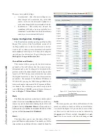
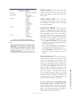
menu to enter the Destinations screen (Figure 3-7);
we’ll set up our mix-minus for output #5.
3. Just to the right of each
Channel
name box , you’ll
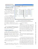
see a “list” icon. Click on the list icon for output #5.
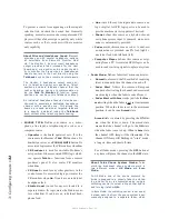
A list of available sources will pop up (Figure 3-8).
Notice that the names and channel numbers of the
sources are both displayed for easy identification.
We’ll choose
Studio 1 Phone
from the list; the list
window closes and you’re returned to the
Destina-
tions
screen. The line for output #5 now displays the
channel number and name of the source.
4. Now comes the step that makes this output a mix-
minus. Each
Destination
entry line has a drop box
at the end; click on the drop-down and choose
To
source
.
Automagic: If the hybrid source is loaded to an
Engine and the engine is generating a mix minus
source already, the list box will show TWO iden-
tical channels for the source — but one will have
a description of “TO:” in front of it. Selecting
this source automatically selects TO SOURCE in
the TYPE box.
Figure 3-8: Picking a source from the list box
5. Click
Apply
.
6. Now point your browser back to your Element Con-
trol Center page (or IO Subsection if you are using
a PowerStation) and choose
GPIO
Configuration
from the menu sidebar. (You may also use a GPIO
Node other than the Power Supply/GPIO or Power-
Station that shipped with your Element, just point
your browser to that node’s IP address instead.)
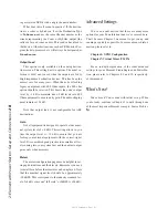
7. The GPIO setup screen uses the same method of as-
signing devices to ports as the Analog Node. Pick
a port to map your hybrid’s contact closures to, us-
ing the list tool, and click
Apply
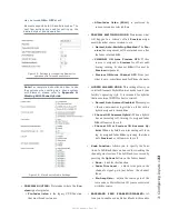
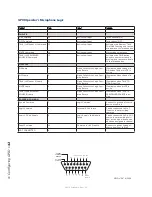
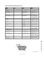
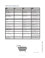
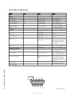
. Figure 3-9 shows
the four port GPIO section of a PowerStation MAIN.
The Element and GPIO node are similar but have
eight ports.
Figure 3-9: GPIO Port Assignment
The process is complete: you’ve made a Source Pro-
file for your phone hybrid, created a mix-minus, mapped
it to an audio output (destination), and associated a GPIO
port for contact closures associated with the source.
To confirm, choose
Options
at the top of any El-
ement fader channel and load your new Phone source.
Press the
Talk
key just below the fader; you’ll see the
Status Symbol shown in Figure 3-10 appear in the win-
dow above the channel to indicate that the operator’s mic
is talking to this telephone hybrid through it’s backfeed
Содержание element v.2.0
Страница 100: ...5 Element Operations 90 2016 Axia Audio Rev 1 8 1 Capital budget may you never decrease for we need new test gear...
Страница 149: ...Appendix A Specifications 139 2016 Axia Audio Rev 1 8 1...
Страница 183: ...Warranty 173 2016 Axia Audio Rev 1 8 1 TCP IP How did we live without thee Analogicly...
Страница 184: ...THIS PAGE INTENTIONALLY LEFT BLANK...
Страница 185: ...THIS PAGE INTENTIONALLY LEFT BLANK...

