2: E
le
m
en
t w
ith P
ow
er
S
ta
tio
n: S
et
up a
nd C
on
ne
ct
io
ns •
15
©2016 Axia Audio- Rev 1.8.1
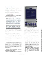
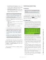
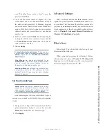
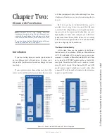
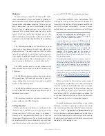
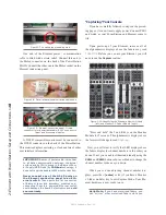
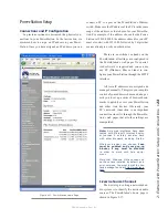
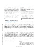
Figure 2-4: Analog and AES Audio Connector
Pin-Outs
INPUT CONNECTORS
Pin
Function Analog/AES
1
Left Ch. Input + / AES +
2
Left Ch. Input - / AES -
3
Right Channel Input +
4
Not Connected
5
Not Connected
6
Right Channel Input -
7
Not Connected
8
Not Connected
Microphone
There are two XLR-F connectors on the rear panel
that are designed for microphone inputs. These con-
nectors use the standard wiring convention for a 3-pin
XLR audio connector. These connectors may have 48-
volt Phantom Power enabled via the PowerStation’s web
page configuration so take appropriate precautions if you
connect anything other than a microphone to these inputs
when Phantom Power is enabled.
GPIO Connections
The PowerStation MAIN and AUX each include four
GPIO ports wired in the same configuration as GPIO
ports on other Axia products. Please refer to Chapter 4:
Configuring GPIO for the functions of these ports and
wiring diagrams for the DB-15 connectors.
In most cases, a GPIO port will be associated with
a single source such as a cd player, studio microphone,
profanity delay, etc. PathfinderPC may also be used to
monitor and control GPIO for advanced applications.
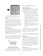
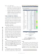
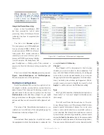
Figure 2-5: GPIO Connector Pin-Outs
The interconnections to GPIO ports will vary de-
pending on the type external equipment being used and
whether or not voltage is supplied by an external device.
Chapter 4: Configuring GPIO provides the details.
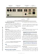
Ethernet Connections
The PowerStation MAIN has three types of Ethernet
connections and it is important to use them as intended
since the internal Ethernet switch is configured in a spe-
cific manner. The types of connectors available are:
• 100 Mbps PoE (Power-over-Ethernet) ports are
designed to be used with future Livewire prod-
ucts that will not use an external power supply
but rather obtain their power over Ethernet from
one of these special Ethernet ports.
• 100 Mbps Ethernet standard ports are used to
connect PC’s or other Livewire devices to your
Livewire network. These devices might include
additional Livewire nodes or PC’s running the
Axia IP-Audio driver.
• 1000 Mbps ports (GIGABIT PORTS) are used
for connections to other PowerStations or for
connections to an Ethernet core switch as de-
scribed below.
In addition to its audio and PSU connections, the
PowerStation AUX unit has a single 100 Mbps Ethernet
connection that is intended to be connected to a 100Mbps
port on its associated PowerStation MAIN.
There are a few different configurations for the two
1000 Mbps Ethernet ports on your PowerStation MAIN.
PowerStation Ring
In this mode, the 1000 Mbps Ethernet ports will be
looped to other PowerStation Main units in a ring con-
figuration. Up to four PowerStation MAIN chassis may
be connected in this manner. This mode provides for
Ethernet fault tolerance using standard Spanning Tree
Protocol. The failure or disconnection of any PowerSta-
tion will not affect the operation of others and any audio
from common sources connected to an operating Power-
Station will continue uninterrupted.
Ethernet Core Switch
Trunk mode for an uplink port supports the connec-
tion of a PowerStation to a 1000 Mbps port on a properly
configured Ethernet core switch.
Содержание element v.2.0
Страница 100: ...5 Element Operations 90 2016 Axia Audio Rev 1 8 1 Capital budget may you never decrease for we need new test gear...
Страница 149: ...Appendix A Specifications 139 2016 Axia Audio Rev 1 8 1...
Страница 183: ...Warranty 173 2016 Axia Audio Rev 1 8 1 TCP IP How did we live without thee Analogicly...
Страница 184: ...THIS PAGE INTENTIONALLY LEFT BLANK...
Страница 185: ...THIS PAGE INTENTIONALLY LEFT BLANK...

