A
pp
en
di
x C
: F
A
Q / D
ia
gn
os
tic
s / M
ai
nt
en
an
ce •
14
6
©2016 Axia Audio- Rev 1.8.1
lowing items:
»
The specified module
»
An overbridge alphanumeric display panel
»
An overbridge window for the display panel
»
A ribbon connector
»
A 1-foot RJ45 patch cable
If you believe any of thse items are missing, please
contact Axia Support immediately.
Tools you’ll need for module installation are:
»
A #1 Philips-head screwdriver
»
A 2.5 mm. hex wrench
»
A
5
/
64
” jeweler’s screwdriver
Before beginning, you’ll need to set the ID for your
new module. Each Element module must have a unique
ID. A quick way of choosing an ID is to count how many
modules are installed on your Element; typically the
factory installs modules with IDs set in numerical order
from left to right (Master Modules should always have
their ID set to “0”; more on this later). So, if you have 4
factory-installed modules in your Element, you can safe-
ly set the ID of your new module to “5”. To set the mod-
ule ID, use a jeweler’s screwdriver to gently rotate the
indicator (shown in Figure C-7) to the desired number.
To begin installation, remove the blanking panel oc-
cupying the position you wish to install your new mod-
ule into. Use the hex wrench to remove the hex-head
screw(s) at the top of the panel.
If your new module has an accompanying overbridge
display, you will need to remove one of Element’s end-
panels in order to insert it. Ascertain which end panel is
closest to the position your new module will be mounted
in; this is the one you’ll remove.
There are eight machine screws that hold each Ele-
ment end panel to the frame: 5 in the “bucket” and 3
under the overbridge (shown in Figure C-8, below). To
access these screws, you’ll need to remove the module
closest to this end panel and tilt the overbridge forward..
Once the screws are removed, the end panel pulls
off easily. Note the locating hole in the end panel that
receives the overbridge hinge pin.
If there are any overbridge displays between the
end of the overbridge and the position in which you’ll
be mounting your alpha panel, you must remove them.
To do so, remove the ribbon connector from the circuit
board by gently pushing the two “ears” on each side of
the connector socket. This will eject the connector.
Note: Ribbon connectors must be connected
to the alphanumeric panels “tail-down”, that is,
with the ribbon emerging from the bottom of
the connector.
You may now slide the disconnected alpha panels
out of the overbridge mounting channel, along with the
blanking panel occupying your new display’s position.
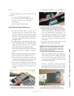
Figure C-7: Setting the module ID
Figure C-8: Locations of end-panel fastening screws
in the overbridge compartment (above) and in the
“bucket” (below).
Содержание element v.2.0
Страница 100: ...5 Element Operations 90 2016 Axia Audio Rev 1 8 1 Capital budget may you never decrease for we need new test gear...
Страница 149: ...Appendix A Specifications 139 2016 Axia Audio Rev 1 8 1...
Страница 183: ...Warranty 173 2016 Axia Audio Rev 1 8 1 TCP IP How did we live without thee Analogicly...
Страница 184: ...THIS PAGE INTENTIONALLY LEFT BLANK...
Страница 185: ...THIS PAGE INTENTIONALLY LEFT BLANK...


