10
:
Po
w
er
S
ta
tion
C
on
tr
ol
s •
1
3
3
©2016 Axia Audio- Rev 1.8.1
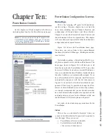
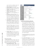
In the example shown in Figure 10-6, we can see
that output pin 1 of the Control Room Monitor GPO is
active. This indicates that a microphone in live in that
room - naturally this is the control for our ON-AIR light.
We can also see GPO pin 2 is also active - that the CR
monitors are dimmed. The cause of dimmed monitors
is the Hybrid in Preview as we can see on GPO pin 3
on port 2.
If all of this seems confusing, please read Chapter
4: Configuring GPIO. Interfacing any electronic sys-
tem to the real world takes some effort, but Livewire
makes it a lot easier by associating this control with the
same Livewire channel that handles your audio stream.
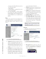
When configuring a GPIO port, you may use the
pop-up selector to choose your Livewire source from the
selection window or you may simply enter the Livewire
channel number into the box if you happen to know it.
As usual - click Apply when you are done.
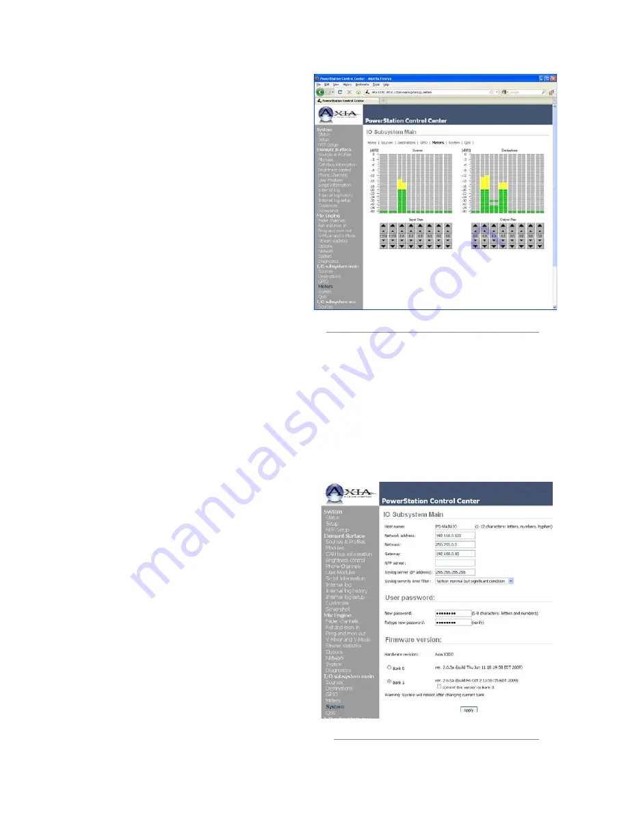
Meters
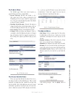
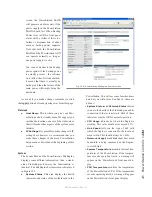
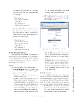
The PowerStation IO Subsystem has meters to assist
with troubleshooting and level calibration.
These meters are peak-reading meters and will show
you how much headroom you have at your audio inputs
and outputs. The Green indicator is considered safe. The
meter bar will change to Yellow at 20 dB below full scale
and it will change to Red at 10 dB below full scale.
To make gain changes, the small arrow will increase
or decrease gain by approximately 0.1 dB. The large ar-
rows will increase or decrease gain by approximately 1.0
dB. We recommend that all system levels be normalized
at 20 dB below full scale. At the output of an audio node
or the PowerStation IO Subsystem, this will be a stan-
dard +4dB. That’s about 1.23 volts for those who want
to measure it with an analog RMS meter.
System
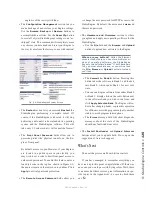
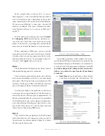
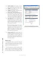
This section has the configuration for the IP settings
of the PowerStation’s I/O subsystem section as well as
the provisions for software updates. Figure 10-8 shows
the web page for this section.
As described previously in this manual, it is recom-
mended that all IP address information be entered in the
PowerStation Setup menu. IP addresses are automatical-
ly assigned to the IO Subsystems and Ethernet switch. If
you make changes to IP settings in this section, they
will be over-written the next time the PowerStation
is restarted.
• Host Name:
You should enter a short, logical
name here to describe the IO Subsystem. We
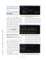
Fig. 10-7: Audio I/O Subsystem - Meters
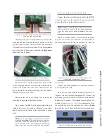
Fig. 10-8: Audio I/O Subsystem - System
Содержание element v.2.0
Страница 100: ...5 Element Operations 90 2016 Axia Audio Rev 1 8 1 Capital budget may you never decrease for we need new test gear...
Страница 149: ...Appendix A Specifications 139 2016 Axia Audio Rev 1 8 1...
Страница 183: ...Warranty 173 2016 Axia Audio Rev 1 8 1 TCP IP How did we live without thee Analogicly...
Страница 184: ...THIS PAGE INTENTIONALLY LEFT BLANK...
Страница 185: ...THIS PAGE INTENTIONALLY LEFT BLANK...

