2: E
le
m
en
t w
ith P
ow
er
S
ta
tio
n: S
et
up a
nd C
on
ne
ct
io
ns •
1
3
©2016 Axia Audio- Rev 1.8.1
PowerStation’s configuration is web-based, so
you’ll need a computer with a web browser. Any
current desktop or notebook PC with an Ethernet
port and a standard Internet browser with Java
support is acceptable.
For Livewire network cable connections, CAT-5e
Ethernet cable is required however many use CAT-6
since it is readily available at a slightly higher cost. For
greater detail on cable selections, we recommend you
read The Axia Guide to Choosing Category Cable avail-
able from
https://www.telosalliance.com/Axia
.
In a larger network with a core switch, always make
certain that power has been applied to your core Eth-
ernet switch and that the switch is properly configured
for multicast as recommended by Axia before powering
your other Axia components.
PowerStation - Front Panel
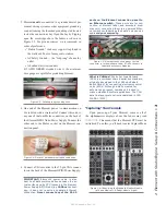
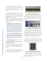
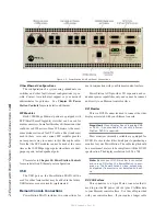
The indicator panel of the PowerStation MAIN,
shown here in Figure 2-2, is very clean. Sorry - there are
no controls for you to push or turn. All configuration and
setup is performed in software through the web browser
interface. The PowerStation AUX is very similar. Differ-
ences are noted in the following section.
Front Panel Indicators
Even though there are no knobs or dials, the front
panel has some very useful indicators that tell you about
the health and status of your PowerStation. In all cases,
solid GREEN indicates normal operating conditions.
PSU
This is a general health indicator for the PowerSta-
tion’s power supply. Solid GREEN is the normal state. A
RED LED indicates a power supply or fuse fault. If you
are using the backup power provided by a PowerStation
AUX, solid GREEN indicates normal health. If the AUX
power LED is ORANGE, the fault is with the PowerSta-
tion MAIN. If a PowerStation MAIN is being used with-
out an AUX unit, a configuration checkbox located in the
MixEngine Options web page, will disable the check for
the redundant power supply and return a GREEN status
for a single power supply.
LINK (PowerStation AUX only)
When illuminated continuously, this LED indicates
that the PowerStation’s Ethernet section is functioning
and that the PowerStation’s network devices are linked.
LIVEWIRE
This indicates that Livewire network traffic present
and multicast streams are properly advertised.
MASTER
Solid GREEN indicates the PowerStation a synchro-
nized as a Master clock to the Livewire network. All oth-
er devices should then be reporting Sync or Slave. There
should be only one Master clock device in a Livewire
network at any given time.
SYNC
Solid GREEN indicates the PowerStation a synchro-
nized as a slave to the Livewire network and the clock
is locked. Flashing GREEN indicates sync packets are
being received, but not locked yet. For the sake of illus-
tration, both Master and Sync are illuminated in Figure
2-2. This condition should never exist in the real world
since a Livewire device is either a master or a sync slave;
never both.
OK (PowerStation MAIN only)
Solid GREEN indicates the PowerStation MAIN is
in a normal state of health. Since several internal condi-
tions are monitored, a RED OK indicator can mean one
or more of several abnormal conditions. A correctable
fault condition will be an over-temperature alarm. Check
to ensure the unit has adequate air flow and that the heat
sinks are only slightly warm - never hot.
Contact Axia tech support for additional assistance.
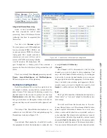
Figure 2-2: PowerStation Front Panel Indicators
Содержание element v.2.0
Страница 100: ...5 Element Operations 90 2016 Axia Audio Rev 1 8 1 Capital budget may you never decrease for we need new test gear...
Страница 149: ...Appendix A Specifications 139 2016 Axia Audio Rev 1 8 1...
Страница 183: ...Warranty 173 2016 Axia Audio Rev 1 8 1 TCP IP How did we live without thee Analogicly...
Страница 184: ...THIS PAGE INTENTIONALLY LEFT BLANK...
Страница 185: ...THIS PAGE INTENTIONALLY LEFT BLANK...

