8: A
dv
an
ce
d E
le
m
en
t C
on
tr
ol
s •
1
1
5
©2016 Axia Audio- Rev 1.8.1
module is working, i.e., communicating with the Ele-
ment CPU.
• The
Firmware Version
field displays the fader firm-
ware version that’s loaded on each module.
At the bottom of the page, you’ll see a lot of informa-
tion pertaining to the health of the Element’s CANBus
communication network. This is for diagnostic purposes
only.
•
Firmware Update:
From time to time, new mod-
ule firmware may become available from Axia.
You may confirm the current Module Firmware
versions installed in your Element and install new
firmware by choosing this menu item.
To update Module Firmware, use the
Browse
and
Upload Image
buttons to install the module
firmware package obtained from Axia Support.
Once a new software image has been uploaded, the
Firmware Update screen will change to notify you
which modules have new firmware available.
Each module must be updated individually. To up-
date a module, simply click on its
Update
link.
Note that updating a module takes it offline
during the update process. While audio playing
through the module’s faders will continue un-
interrupted, keep in mind that while updating
(usually about 10-15 seconds) you will not be
able to adjust gain or turn faders on or off on
the module being updated.
CAN Bus Information Menu
This screen shows statistics about CANBus commu-
nications between Element’s CPU and control surface.
Note that you will need Java to view the graphical infor-
mation presented in this window. During normal opera-
tion, you will see two lines, one red and one blue. These
lines provide a graphical representation of the CANBus
transmit and receive data. You will see a momentary
spike only when a button is pressed on the console or
on a CANBus accessory panel. If these lines show er-
ratic activity, or if they do not follow the same general
trends, you may have a CANBus cabling or termination
problem.
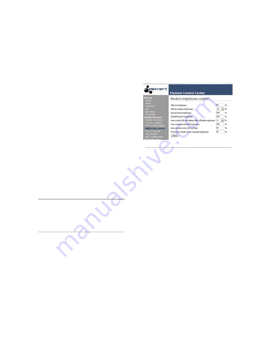
Brightness Control Menu
This menu offers several useful options for fine-tun-
ing your Element’s various LED and LCD displays to
your studio’s ambient lighting. All values are expressed
in percent.
Fig. 8-8: Module Brightness Control
•
LED Icon Brightness
lets you adjust the luminance
of the Status Symbols / fader numbers on the Ele-
ment overbridge (the little windows just above the
source identifiers).
•
LED Text Display Brightness
does the same for
the alphanumeric displays that indicate what source
is loaded to each fader channel.
•
Round Button Brightness
adjusts the luminance
of the interior LEDs that illuminate Element’s
Op-
tions
,
PGM 1-4
,
Monitor
,
Headphone
and other
selection keys.
•
ON / OFF Button Brightness:
You can probably
figure this one out on your own :^)
•
User Module LED Text Display Flash Off-State
Brightness:
If you have any SmartSwitch modules
or accessory panels installed, you can use this setting
to determine how “dark” display text is when that
text flashes for attention. A value of
0
makes the text
flash from completely on to completely off; a higher
value keeps the text slightly illuminated in its “off”
state.
•
User Module Button LCD Brightness:
This af-
fects only SmartSwitch modules and panels. Deter-
mines how bright the backlighting is for each Smart-
Switch button’s colored LCD screen.
•
User Module Button LCD Contrast:
Adjusts the
Содержание element v.2.0
Страница 100: ...5 Element Operations 90 2016 Axia Audio Rev 1 8 1 Capital budget may you never decrease for we need new test gear...
Страница 149: ...Appendix A Specifications 139 2016 Axia Audio Rev 1 8 1...
Страница 183: ...Warranty 173 2016 Axia Audio Rev 1 8 1 TCP IP How did we live without thee Analogicly...
Страница 184: ...THIS PAGE INTENTIONALLY LEFT BLANK...
Страница 185: ...THIS PAGE INTENTIONALLY LEFT BLANK...


