A
pp
en
di
x C
: F
A
Q / D
ia
gn
os
tic
s / M
ai
nt
en
an
ce •
1
47
©2016 Axia Audio- Rev 1.8.1
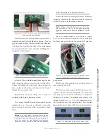
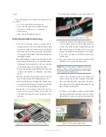
Carefully slide your new alphanumeric panel into the
mounting channel. Note that the metal portion of the dis-
play has rounded edges which fit into the round frontmo-
st channel; the circuit-board portion of the display must
have its top and bottom edges located in the first groove
behind the round channel.
After all of the overbridge panels have been located
in the mounting channel, reconnect their ribbon cables.
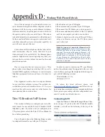
Connect the ribbon cable that came with your new dis-
play, and thread it from the overbridge into the “bucket”
through the passage provided.
Re-mount the end panel, taking care to locate the
overbridge hinge pin in the hole provided.
Now, connect the RJ45 patch cable supplied in your
module kit to any free jack on Element’s connection
panel, located in the center of the overbridge compart-
ment.
Note: You’ve probably noticed that 4-space
modules have two RJ45 connectors on their un-
dersides. These are “daisy chain” connectors; if
all of the jacks on your Element’s connection
panel are in use, you can connect a new module
to the unused jack on any other module.
Connect the other end of the patch cable to the RHJ45
connector located on the bottom of your new module,
connect the alpha display ribbon connector.
Note: Ribbon connectors must be connected to
the modules “tail-up”, with the cable emerging
from the connector toward the top of the mod-
ule.
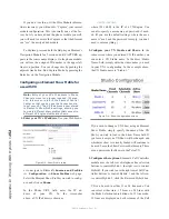
Your new module should look as shown in Figure
C-11. Once all cables are connected, seat the module in
the frame and secure it with the provided 2.5 mm hex-
head screws.
Replace any other modules you may have removed,
and secure them as well.
The final step in the module installation process is to
“capture” the new console configuration. To enter Cap-
ture Mode, press and hold the
*
and
2
keys on the Master
Module for 5 seconds. The alphanumeric displays will
change to read
Capture Mode
; this enumerates all of
the installed faders in the control surface. Press the
En-
ter
or
#
key to exit Capture Mode; your new module is
Figure C-10: Detail of overbridge mounting channel
Figure C-9: Location of alpha display ribbon connectors as
seen from rear of overbridge
Figure C-11: Reverse view of connected module. Note
ribbon cable is connected “tail-up”.
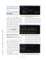
Figure C-12: Alpha display indicates Capture Mode
Содержание element v.2.0
Страница 100: ...5 Element Operations 90 2016 Axia Audio Rev 1 8 1 Capital budget may you never decrease for we need new test gear...
Страница 149: ...Appendix A Specifications 139 2016 Axia Audio Rev 1 8 1...
Страница 183: ...Warranty 173 2016 Axia Audio Rev 1 8 1 TCP IP How did we live without thee Analogicly...
Страница 184: ...THIS PAGE INTENTIONALLY LEFT BLANK...
Страница 185: ...THIS PAGE INTENTIONALLY LEFT BLANK...

