4: C
on
fig
uri
ng G
PI
O •
57
©2016 Axia Audio- Rev 1.8.1
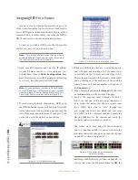
indicator representing Output Pin 2 – the
Off Lamp
logic command – is high. Turning the channel
On
,
we see Pin 4 pulse briefly before Pin 1 goes high:
the GPIO has just sent a
Start
pulse, then lit the
On
Lamp. If you turn the channel
Off
again, you’ll
observe a
Stop
pulse, and the
Off Lamp
command
once again become active.
See how easy that was? Simply assigning an existing
audio source to a GPIO port automagically configures
the port for the type of device supplying the audio, and
send the appropriate logic commands to that port when
the source is assigned to a Element channel.
A word about the GPIO Ports
Input Connections
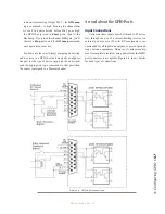
Current on these inputs must be limited to 20 mA or
less, through the use of a current-limiting resistor. An
external power source (24 volts DC maximum) is rec-
ommended for all inputs and outputs, to prevent ground
loops between equipment. However, if customer equip-
ment is completely isolated, using power from the GPIO
port connectors is acceptable. Figure 4-4 shows details
for both types of connections:
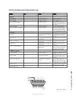
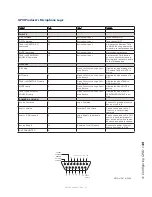
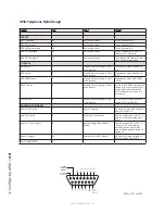
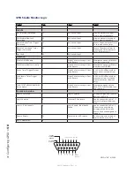
Figure 4-4 GPIO input connections
Содержание element v.2.0
Страница 100: ...5 Element Operations 90 2016 Axia Audio Rev 1 8 1 Capital budget may you never decrease for we need new test gear...
Страница 149: ...Appendix A Specifications 139 2016 Axia Audio Rev 1 8 1...
Страница 183: ...Warranty 173 2016 Axia Audio Rev 1 8 1 TCP IP How did we live without thee Analogicly...
Страница 184: ...THIS PAGE INTENTIONALLY LEFT BLANK...
Страница 185: ...THIS PAGE INTENTIONALLY LEFT BLANK...

