1:
E
le
me
nt
w
ith
S
tu
dio
En
gin
e:
S
et
up
&
C
on
ne
ct
io
ns
•
3
©2016 Axia Audio- Rev 1.8.1
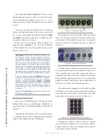
2. Element must be connected to a grounded metal per-
manent wiring system or other equipment grounding
conductor using the threaded grounding stud located
inside the connections bay. Open the bay by flipping
open the overbridge above the faders, as shown in
Figure 1-2. For ground sources, we recommend, in
order of preference:
»
“Station Ground,” the heavy copper strap found in
the walls and floors of many radio studios.
»
AC Safety Ground — the “3rd prong” of a nearby
outlet.
»
A bonded electrical conduit.
#12 AWG GREEN stranded wire is the minimum
wire gauge acceptable for grounding Element.
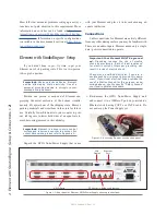
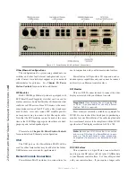
Figure 1-3: Locating the grounding stud.
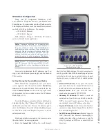
3. One end of the Element power / communication ca-
ble is fitted with a strain relief. Connect this end to
any one of the four Molex connectors on the back of
the Element GPIO Node/Power Supply. Connect the
other end to the
Molex socket on the Element con-
nection panel.
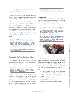
Figure 1-4: Detail of data/communication cable ends.
4. Connect a VGA monitor to the 15-pin VGA connec-
tor on the back of the Element GPIO/Power Supply.
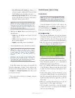
IMPORTANT: Element’s power cable is also
host to all data communication between the ac-
tual surface and its CPU (housed in the Element
Power Supply/GPIO Node) by CANbus technol-
ogy; it does not require a separate Ethernet
connection. Never connect any of the RJ-45
ports on the Element connection panel to
an Ethernet switch. These ports are for con-
nection of Element fader and accessory mod-
ules only; connecting them to a powered Ether-
net switch could damage the board’s electronics
and void your warranty.
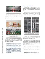
Figure 1-5: Element connection panel. Circled
connector is for power/data cable; RJ-45’s connect to
fader and accessory modules.
What is CANbus? Controller Area Network
(CAN) is a multicast shared serial bus standard,
originally developed in the 1980s by Robert
Bosch GmbH, for connecting electronic control
units (ECUs). Although initially created for
automotive purposes, nowadays it is used in
many embedded control applications. The CAN
data link layer protocol is standardized in ISO
11898-1 (2003).
“Capturing” Your Console
Upon power-up of your Element, some or all of
the alphanumeric displays above the faders may read
INACTIVE
. This means that the Element CPU must be
initialized. To do this, you’ll need to enter Capture Mode.
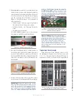
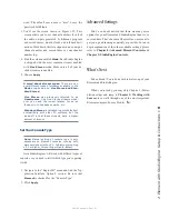
Figure 1-6: Identifying the Standard Monitor Module
(left) and M 2-Fader Module (right).
Содержание element v.2.0
Страница 100: ...5 Element Operations 90 2016 Axia Audio Rev 1 8 1 Capital budget may you never decrease for we need new test gear...
Страница 149: ...Appendix A Specifications 139 2016 Axia Audio Rev 1 8 1...
Страница 183: ...Warranty 173 2016 Axia Audio Rev 1 8 1 TCP IP How did we live without thee Analogicly...
Страница 184: ...THIS PAGE INTENTIONALLY LEFT BLANK...
Страница 185: ...THIS PAGE INTENTIONALLY LEFT BLANK...


