2: E
le
m
en
t w
ith P
ow
er
S
ta
tio
n: S
et
up a
nd C
on
ne
ct
io
ns •
1
9
©2016 Axia Audio- Rev 1.8.1
are in Capture Mode. A motorized fader that is
“slaved” to a master fader will move automati-
cally to mirror the movements of the master.
Mirrored faders both control gain for the same
source, but the master can override the setting
of the slave — useful for “split” Element setups
where talent has a local set of faders that may
be used to control certain sources, but you still
want the Board Operator to have master control.
To mirror a fader, press the Options key above
the fader you wish to make the “slave”. An apos-
trophe (
‘
) will be displayed next to its numeric
indicator. Pressing the fader’s PGM1 and PGM2
keys will change the numeric indicator, indicating
the “Master” to which this fader is now slaved; a
display reading
2’
means that the fader is slaved
to fader 2.
Pressing the Options key again returns the fad-
er to non-mirrored mode.
Short Navigation Tutorial
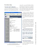
There are several different ways to change on-screen
options. The first way is with Element’s SoftKnobs, lo-
cated directly above the Monitor Module and shown in
Figure 2-11.
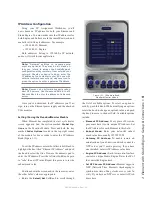
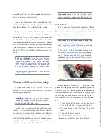
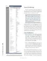
Figure 2-11: Element SoftKnobs.
If your Element is equipped the standard Monitor
module, you will have six SoftKnobs as shown. The
2-fader Master module has three SoftKnobs. These
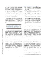
knobs are context-sensitive. When any of Element’s set-
up modes are activated using the options keys on the fad-
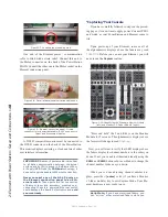
ers or Master Module, you’ll see a corresponding row of
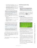
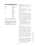
“knobs” represented onscreen, as shown in Figure 2-12.
Figure 2-12: On-screen SoftKnobs.
Note that there are sometimes functions shown both
above and below the on-screen SoftKnobs. When a func-
tion is presented above the knob, turning that knob ac-
complishes that function. When a function is presented
below the knob, pushing in gently on the corresponding
SoftKnob activates that function. The example shown in
Figure 2-14 is from the IP Address Book screen - rotate
to “select”; push to “take”.
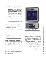
If your Element is equipped with the standard Moni-
tor Module, you can also navigate using the control knob,
directional keys and Enter key located at the lower right-
hand corner of the module, as shown in Figure 2-10.
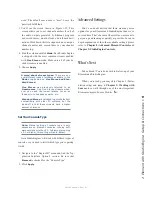
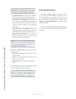
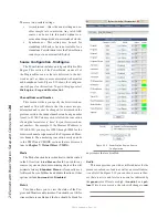
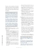
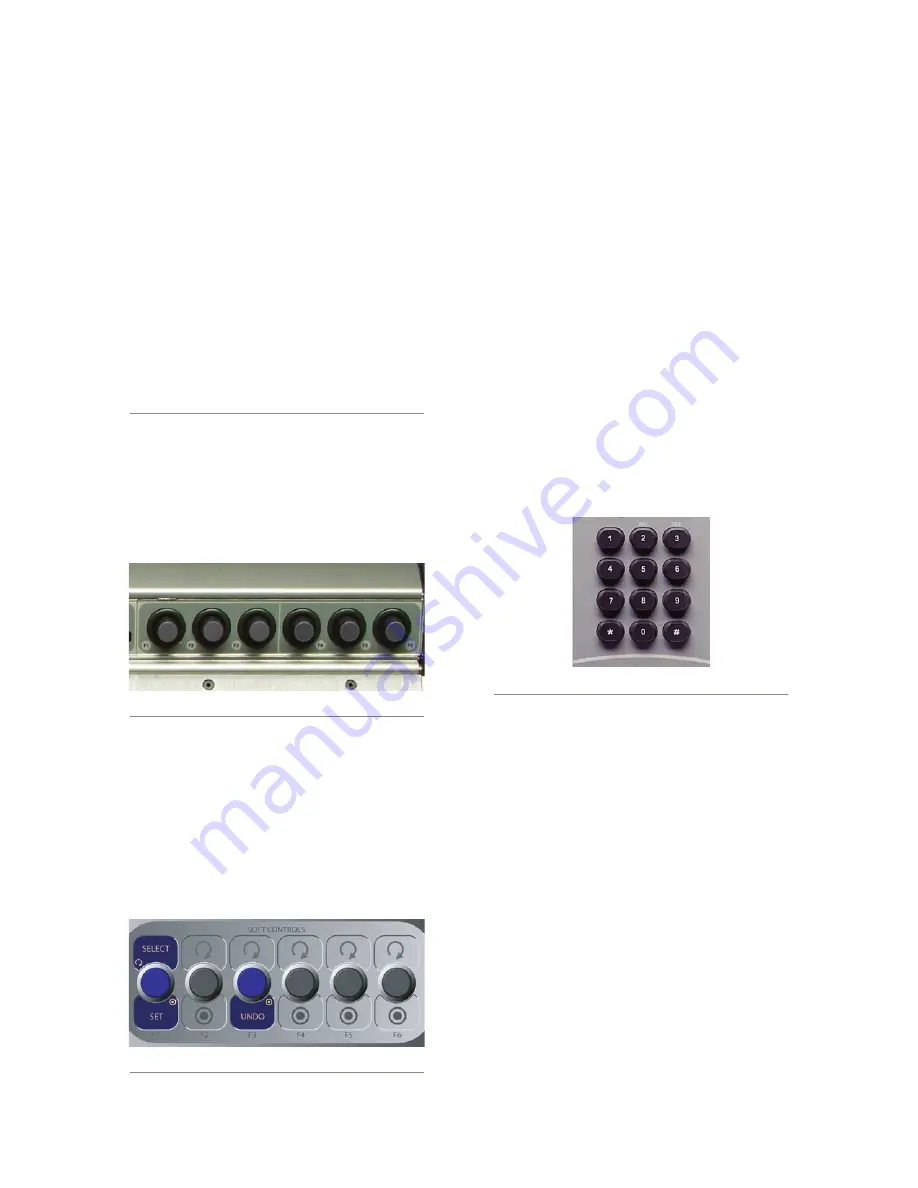
Additionally, whenever numeric input is required
(like entering IP addresses), you can use the numeric
keypad located just above the Navigation Keys (Figure
2-13) to enter numbers directly.
Figure 2-13: Master Module numeric keypad.
IP Address Configuration
Using your IP Assignment Worksheet, you’ll now
choose an IP address for your PowerStation. Note that
since the PowerStation MAIN is a multi-function unit,
it will actually utilize three IP addresses. The first ad-
dress is assigned to the Element console. Once this as-
signment has taken effect, the next two addresses will
be assigned to the PowerStation Ethernet switch and the
I/O section. For example, if you assign 192.168.0.100
to the Element, the PowerStation will automatically as-
sign 192.168.0.101 to its internal Ethernet switch and
192.168.0.102 to its I/O module. If a PowerStation AUX
is connected, 192.168.0.103 would automatically be as-
signed to the AUX unit. Be sure to accommodate these
IP addresses in you IP scheme.
A PowerStation AUX may be used as a standalone
Содержание element v.2.0
Страница 100: ...5 Element Operations 90 2016 Axia Audio Rev 1 8 1 Capital budget may you never decrease for we need new test gear...
Страница 149: ...Appendix A Specifications 139 2016 Axia Audio Rev 1 8 1...
Страница 183: ...Warranty 173 2016 Axia Audio Rev 1 8 1 TCP IP How did we live without thee Analogicly...
Страница 184: ...THIS PAGE INTENTIONALLY LEFT BLANK...
Страница 185: ...THIS PAGE INTENTIONALLY LEFT BLANK...

