background image

244

9  MANUFACTURER FUNCTIONS
9.5  Simple cam function

Clutch

Use the clutch when starting or stopping the servo motor by transmitting or shutting commands from the main shaft to the 
output axis module side with the clutch on/off.
Set whether or not to use the clutch control with [Cam control data No. 36 - Main shaft clutch control setting].
Although the clutch ON/OFF can be changed during cam control, the setting of [Cam control data No. 36] cannot be changed 
from "1 (Clutch command ON/OFF)" to "0 (No clutch)" during cam control.

ON control mode

"No clutch"

When [Cam control data No. 36 - Main shaft clutch control setting] is set to "0 (No clutch)", other clutch parameters are not 
used due to direct coupled operation.

Clutch command ON/OFF

The clutch is turned on/off by turning on/off bit 11 of Control DI2 (2D02h).
(Settings in the OFF control mode are not used in the clutch command ON/OFF mode.)

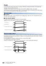
Clutch smoothing method

Smoothing is processed with the time constant set in [Cam control data No. 43 Main shaft clutch smoothing time constant] at 
clutch ON/OFF. Even after clutch ON smoothing is completed, smoothing is processed with the set time constant if the speed 
of the input values changes.
The travel distance from turning on to off of the clutch does not change with smoothing.
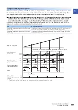
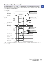
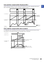
Time constant system exponential curve smoothing
Set [Cam control data No. 42 - Main shaft clutch smoothing system] to "1 (Time constant system (Exponent))".

t

t

Control DI 2 bit 11

Status DO 2 bit 11

Current value before clutch input

Travel distance after clutch output

t

t

63 %

63 %

Speed before clutch processing

Speed after clutch smoothing

Clutch smoothing time constant

Summary of Contents for MELSERVO-MR-J4 GF Series

Page 1: ...General Purpose AC Servo CC Link IE Field Network Interface Servo Amplifier Instruction Manual CC Link IE Field Network Basic MR J4 _GF_ MR J4 _GF_ RJ ...

Page 2: ......

Page 3: ...ions Please follow the instructions of both levels because they are important to personnel safety What must not be done and what must be done are indicated by the following diagrammatic symbols In this Instruction Manual instructions at a lower level than the above instructions for other functions and so on are classified into POINT After reading this Instruction Manual keep it accessible to the o...

Page 4: ...an electric shock always connect the protective earth PE terminal marked of the servo amplifier to the protective earth PE of the cabinet To avoid an electric shock insulate the connections of the power supply terminals CAUTION Install the servo amplifier servo motor and regenerative resistor on incombustible material Installing them directly or close to combustibles will lead to smoke or a fire A...

Page 5: ...urst damage etc may occur Ensure that polarity is correct Otherwise a burst damage etc may occur The servo amplifier heat sink regenerative resistor servo motor etc may be hot while the power is on and for some time after power off Take safety measures such as providing covers to avoid accidentally touching them by hands and parts such as cables The following instructions should also be fully note...

Page 6: ...ill the following environment When the product has been stored for an extended period of time contact your local sales office When handling the servo motor be careful with the sharp edges of the servo motor The servo amplifier must be installed in a metal cabinet When fumigants that contain halogen materials such as fluorine chlorine bromine and iodine are used for disinfecting and protecting wood...

Page 7: ...trol output should be fitted in the specified direction Otherwise the converter unit and the drive unit will malfunction and will not output signals disabling the emergency stop and other protective circuits When the wires are not tightened enough to the terminal block the wires or terminal block may generate heat because of the poor contact Be sure to tighten the wires with specified torque Conne...

Page 8: ...ty Before resetting an alarm make sure that the run signal of the servo amplifier is off in order to prevent a sudden restart Otherwise it may cause an accident Use a noise filter etc to minimize the influence of electromagnetic interference Electromagnetic interference may affect the electronic equipment used near the servo amplifier Do not burn or destroy the servo amplifier Doing so may generat...

Page 9: ...ected restart after an instantaneous power failure After an earthquake or other natural disasters ensure safety by checking the conditions of the installation mounting wiring and equipment before switching the power on to prevent an electric shock injury or fire CAUTION Make sure that the emergency stop circuit operates properly such that an operation can be stopped immediately and a power is shut...

Page 10: ...reaches the end of its useful life Write to the EEP ROM due to parameter setting changes Write to the EEP ROM due to device changes STO FUNCTION OF THE SERVO AMPLIFIER When using the STO function of the servo amplifier refer to chapter 13 of MR J4 _GF_ RJ Servo Amplifier Instruction Manual Motion Mode For the MR J3 D05 safety logic unit refer to app 5 of MR J4 _GF_ RJ Servo Amplifier Instruction M...

Page 11: ...O Servo Motor Instruction Manual Vol 3 1 SH NA 030113ENG MELSERVO Linear Servo Motor Instruction Manual 2 SH NA 030110ENG MELSERVO Direct Drive Motor Instruction Manual 3 SH NA 030112ENG MELSERVO Linear Encoder Instruction Manual 2 4 SH NA 030111ENG EMC Installation Guidelines IB NA 67310ENG Item Detailed explanation Installation MR J4 _GF_ Chapter 2 Signals and wiring MR J4 _GF_ chapter 3 Normal ...

Page 12: ...figuration including peripheral equipment 22 CHAPTER 2 CC Link IE FIELD NETWORK BASIC PROTOCOL 24 2 1 Description 24 2 2 Message format 24 2 3 Link device 25 RYn mapping pt idx jg hm 25 RXn mapping pt idx jg hm 25 RWwn mapping pt idx jg hm 25 RWrn mapping pt idx jg hm 26 2 4 Mapping data details of link device 27 CHAPTER 3 SLMP 28 3 1 Description 28 3 2 Message format 29 Request message format 29 ...

Page 13: ...ing mode hm 62 Function explanation 62 Related object 63 Usage 70 CiA 402 type homing method 72 Operation example of Manufacturer specific Homing method 84 6 2 Point table mode pt 98 About point table mode pt 98 Automatic operation using point table 102 Function and related objects 106 Setting method of point tables using MR Configurator2 109 Setting method of point tables using objects 112 Operat...

Page 14: ...R 8 TROUBLESHOOTING AT POWER ON 203 CHAPTER 9 MANUFACTURER FUNCTIONS 205 9 1 Stroke end 205 9 2 One touch tuning 207 Related object 207 Procedure of one touch tuning via a network 207 9 3 Machine diagnosis function 208 9 4 Servo amplifier life diagnosis function 208 9 5 Simple cam function 209 Outline of simple cam function 209 Simple cam function block 210 Simple cam specification list 211 Contro...

Page 15: ...e 2D69h 289 Target speed No 2DD1h 289 Manufacturer Device Name 2 2D30h 290 Manufacturer Software Version 2 2D32h 290 Serial Number 2 2D33h 291 Servo motor serial number 2D46h 291 10 4 Object dictionary details objects in the 6000s 292 Quick stop option code 605Ah 292 Halt option code 605Dh 292 Control mode display 6061h 292 Software Position Limit 607Dh 293 Polarity 607Eh 293 Feed constant 6092h 2...

Page 16: ...r2 and GX Works Slide switch setting Select CC Link IE Field Network Basic communication by turning the slide switch 1 SW1 1 OFF and the slide switch 2 SW1 2 ON Refer to the following for details Page 42 Switches Parameter setting Select a positioning mode with Pr PA01 Operation mode Item Detailed explanation Function block diagram MR J4 _GF_ section 1 2 Combinations of servo amplifiers and servo ...

Page 17: ...onstants with Pr PT51 System Signed absolute value command method incremental value command method Torque limit Limits the servo motor torque Control mode Point table mode pt Each positioning operation Point table No input method Operates each positioning based on position command and speed command Automatic continuous positioning operation Varying speed operation 2 to 255 speeds automatic continu...

Page 18: ...tch and index pulse Method 11 Homing on home switch and index pulse Method 12 Homing without index pulse Method 19 Homing without index pulse Method 20 Homing without index pulse Method 21 Homing without index pulse Method 22 Homing without index pulse Method 23 Homing without index pulse Method 24 Homing without index pulse Method 27 Homing without index pulse Method 28 Homing on index pulse Meth...

Page 19: ...n settable Shortest rotating indexer Positioning to the specified station Rotates in the shorter direction from the current position Jog mode jg JOG operation Executes an inching operation via a network based on speed command set in Pr PT65 When the servo motor is stopping deceleration to a stop is executed regardless of the station Station JOG operation Executes an inching operation via a network...

Page 20: ...re the servo motor is driven according to the commands of the travel distance speed and others stored in the specified point table No in the commutation with a controller This control mode is not in CiA 402 standard Mitsubishi Electric original Page 98 Point table mode pt Indexer mode idx In this control mode the servo motor is driven to the station specified in the communication with a controller...

Page 21: ...y for positioning operation program operation and single step feed Page 47 Test operation mode MR J4 _GF_ section 4 5 Analog monitor output Outputs servo status with voltage in real time Pr PC09 Pr PC10 MR Configurator2 Using a personal computer you can perform the parameter setting test operation monitoring and others When using MR Configurator2 with an Ethernet connection use a servo amplifier w...

Page 22: ...4 _GF_ section 7 7 CC Link IE Field Network Basic CC Link IE Field Network Basic enables fixed cycle communication between the master and slave stations using a general purpose Ethernet connector The parameters of servo amplifiers can be set read written and monitored Page 24 CC Link IE FIELD NETWORK BASIC PROTOCOL SLMP SLMP SeamLess Message Protocol is a protocol to access SLMP compatible devices...

Page 23: ...oints 64 bytes IP address IPv4 range 0 0 0 1 to 223 255 255 254 Use the same network address for both the master and slave stations Default value 192 168 3 0 Subnet mask Default value recommended 255 255 255 0 Message format Page 24 CC Link IE FIELD NETWORK BASIC PROTOCOL Physical layer 100BASE TX Communication connector RJ45 1 port CN1A Communication cable CAT5e shielded twisted pair 4 pair strai...

Page 24: ...ppendix 1 The diagram shows MR J4 20GF RJ CAUTION Connecting a servo motor of the wrong axis to U V W or CN2 of the servo amplifier may cause a malfunction CN4 CN5 P C L11 L21 P3 P4 MR Configurator2 CN3 CN8 CN2 CN2L 4 W V U L1 L2 L3 1 MC 3 R S T D 5 CN1A CN1B Power supply 2 Personal computer Molded case circuit breaker MCCB Magnetic contactor To safety relay or MR J3 D05 safety logic unit Junction...

Page 25: ...hen dynamic brake deceleration is not required delay the time to turn off the magnetic contactor 4 This is for MR J4 _GF RJ servo amplifier MR J4 _GF servo amplifier does not have CN2L connector When using MR J4 _GF RJ servo amplifier in the linear servo system or in the fully closed loop system connect an external encoder to this connector Refer to section 1 1 of MR J4 _GF_ RJ Servo Amplifier Ins...

Page 26: ...the command to be sent Link devices RWr RWw RX and RY are used for data communication The master station controller refreshes links by sending and receiving the request and response messages at a constant cycle The servo amplifier reads the received data as an object dictionary to drive a servo motor and return monitor data 2 2 Message format The following shows the request message format to be us...

Page 27: ...n depends on the station No setting RWwn mapping pt idx jg hm Master station Servo amplifier RYn Device No 1 Device Symbol Remark RYn0 to RY n 3 E Unavailable RY n 3 F Cyclic communication ready command CSR Servo amplifier Master station RXn Device No 1 Device Symbol Remark RXn0 to RX n 3 E Unavailable RX n 3 F Cyclic communication ready SSR Master station Servo amplifier RWwn Device No 1 Index De...

Page 28: ...display RWrn01 6041 Statusword RWrn02 6064 Position actual value RWrn03 RWrn04 606C Velocity actual value RWrn05 RWrn06 60F4 Following error actual value RWrn07 RWrn08 6077 Torque actual value RWrn09 2D11 Status DO 1 RWrn0A 2D12 Status DO 2 RWrn0B 2D13 Status DO 3 RWrn0C 2D15 Status DO 5 RWrn0D 2D17 Status DO 7 RWrn0E 2D68 Point Demand value RWrn0F 2D69 Point actual value RWrn10 RWrn11 2A42 Curren...

Page 29: ...2 CC Link IE FIELD NETWORK BASIC PROTOCOL 2 4 Mapping data details of link device 27 2 2 4 Mapping data details of link device Page 252 OBJECT DICTIONARY ...

Page 30: ...he binary code It is not compatible with the ASCII code For the compatibility of SLMP with external devices refer to manuals for external devices In SLMP a command that a master station external device sends to slave stations servo amplifiers is called a request message and a command that the slave stations servo amplifiers send back to the master station external device is called a response messa...

Page 31: ...stination network No Request destination station No Request data length Monitoring timer header header header Request data Ethernet UDP IP SLMP Request destination multi drop station No Request destination module I O No Footer Subheader Request destination network No Request destination station No Request data length Monitoring timer header header header Request data Ethernet UDP IP SLMP SLMP Requ...

Page 32: ... until the processing is completed 0001h to FFFFh 1 to 65535 Waiting time Unit 0 25 s Request data Variable Little Specify the command sub command and data that indicate the request content Command 2 bytes Little Page 31 Command Sub command 2 bytes Little Page 31 Command Response data length 2 bytes Little The data length from the end code to the response data at normal completion or to the error ...

Page 33: ...sub commands specified by using the CiA 402 object from the external device to the servo amplifier Page 35 SDO Object SubID Block Download CiA 402 object sub ID continuous write NodeSearch 0E30h 0000h Detects the server device in the network IPAddressSet 0E31h 0000h Sets the IP address of the server device in the network Model code read 0101h 0000h Reads the servo amplifier model Service SLMP Desc...

Page 34: ...a value L H L H L H L H 20h 40h 01h 00h Refer to the following for details Page 32 Item list End code Index Sub Index Reserved Number of data value Read data L H L H L H L or H variable 00h 00h Refer to the following for details Page 32 Item list Item Size Endian Description Command 2 bytes Little 4020h Sub command 2 bytes Little 0001h Index 2 bytes Little Specify Index of the object Page 252 OBJE...

Page 35: ...Write data L H L H L H L H L or H variable 20h 40h 02h 00h Refer to the following for details Page 33 Item list End code Index Sub Index Reserved Number of data value L H L H L H 00h 00h Refer to the following for details Page 33 Item list Item Size Endian Description Command 2 bytes Little 4020h Sub command 2 bytes Little 0002h Index 2 bytes Little Specify Index of the object Page 252 OBJECT DICT...

Page 36: ... Sub Index Reserved Number of data value L H L H L H L H 20h 40h 05h 00h Refer to the following for details Page 34 Item list End code Index Sub Index Reserved Number of data value Read data L H L H L H L or H variable 00h 00h Refer to the following for details Page 34 Item list Item Size Endian Description Command 2 bytes Little 4020h Sub command 2 bytes Little 0005h Index 2 bytes Little Specify ...

Page 37: ...ex Reserved Number of data value Write data L H L H L H L H L or H variable 20h 40h 06h 00h Refer to the following for details Page 35 Item list End code Index Sub Index Reserved Number of data value L H L H L H 00h 00h Refer to the following for details Page 35 Item list Item Size Endian Description Command 2 bytes Little 4020h Sub command 2 bytes Little 0006h Index 2 bytes Little Specify Index o...

Page 38: ...ead only object A value is written to an object that is not the Read only object for all AL states but Write disabled for the present AL state CCC7h A value is written to the object mapped to a response message The following writes are performed when the object mapped to a response message is not allowed to be changed A value other than 0 is written to Sub Index 0 A value is written to the corresp...

Page 39: ... refer to the section indicated in the detailed explanation field MR J4 _GF_ means MR J4 _GF_ RJ Servo Amplifier Instruction Manual Motion Mode WARNING When executing a test run follow the notice and procedures in this instruction manual Otherwise it may cause a malfunction damage to the machine or injury Do not operate the switches with wet hands Otherwise it may cause an electric shock CAUTION B...

Page 40: ...67 PARAMETERS Refer to chapter 5 of MR J4 _GF_ RJ Servo Amplifier Instruction Manual Motion Mode 5 Test operation of the servo motor alone in test operation mode In the test operation operate the servo motor at the lowest speed possible with the servo motor disconnected from the machine and check whether the servo motor rotates correctly Page 47 Test operation mode 6 Network setting check Check th...

Page 41: ...force at a speed of 3000 r min or higher it may cause a position mismatch Make sure that the servo motor is not rotated before switching the power on IP address setting Use a twisted pair cable compliant with Ethernet Category 5e 1000BASE T or higher as an Ethernet cable The maximum cable length between nodes is 100 m Use a hub with a transmission speed of 100 Mbps or faster when branching the Eth...

Page 42: ...ion Manual Motion Mode After setting the parameters turn off the power as necessary Then switch power on again to enable the parameter values Connection with controller Set up the controller by following the manual of the controller used Servo on Enable the servo on with the following procedure 1 Switch on main circuit power supply and control circuit power supply 2 Transmit the servo on command f...

Page 43: ...hut off and the servo motor coasts Ready off command The base circuit is shut off and the dynamic brake operates to stop the servo motor Quick stop command The servo motor decelerates to a stop Error occurrence 2 The servo motor decelerates to a stop Cyclic communication ready command off The servo motor decelerates to a stop Servo amplifier Alarm occurrence The servo motor decelerates to a stop W...

Page 44: ... the slide switches SW1 causes the mode to change to an operation mode for manufacturer setting and off to appear on the display This mode is not available Set the slide switches SW1 correctly according to this section Cycling the main circuit power supply and control circuit power supply enables the setting of each switch The following diagram explains the slide switches and rotary switches WARNI...

Page 45: ...riving by test operation from MR Configurator2 via an Ethernet connection is possible Once the test operation mode is entered the servo amplifier will not receive controller commands until the power of the servo amplifier is cycled Rotary switches SW2 SW3 Set the identification number of the servo amplifier in hexadecimal From 00h 0 to FFh 255 can be set The set value is used as the 4th octet of t...

Page 46: ...etwork initial communication status are displayed in that order For example the following shows when AL 16 1 Encoder initial communication Receive data error 1 is occurring Status 1 digit Identification No 2 digits b Indicates ready off and servo off status C Indicates ready on and servo off status d Indicates ready on and servo on status After 0 8 s After 0 8 s Status Alarm No Blank After 0 2 s A...

Page 47: ... Blinking When an alarm or a warning occurs the alarm No or the warning No is shown After 0 8 s Ready on servo off Blank Servo on When AL E1 Overload warning 1 occurs at identification No 1 Example Blinking Ready on servo on After 0 8 s Blinking Normal operation After 0 8 s Blank During a warning that does not cause servo off a decimal point on the LED of the third digit indicates the servo on sta...

Page 48: ... The ready off command was received 1 Ready on servo off The servo off command was received 1 Ready on servo on The servo on command was received 1 Alarm occurring An alarm or warning has occurred in the servo amplifier 2 Alarm and warning The alarm No and the warning No that occurred are displayed 4 CPU error A CPU watchdog error has occurred 1 Test operation mode 3 During test operation JOG oper...

Page 49: ...rvo motor disconnected from the machine use the test operation mode and check whether the servo motor rotates correctly Refer to the following for the test operation mode Page 47 Test operation mode 2 Test operation of the servo motor alone by commands In this step confirm that the servo motor rotates correctly with the commands from the master station controller Give a low speed command at first ...

Page 50: ...operation screen of MR Configurator2 Operation pattern Operation method When the check box of Rotation only while the CCW or CW button is being pushed is checked When the check box of Rotation only while the CCW or CW button is being pushed is not checked Item Initial value Setting range Servo motor speed r min 200 0 to Maximum speed Accel decel time constant ms 1000 0 to 50000 Operation Screen op...

Page 51: ...to the MR Configurator2 Installation Guide Output signal DO forced output Output signals can be switched on off forcibly independently of the servo status Use this function for checking output signal wiring etc Perform on the DO forced output screen of MR Configurator2 Item Initial value Setting range Travel distance pulse 4000 0 to 99999999 Servo motor speed r min 200 0 to Maximum speed Accel dec...

Page 52: ...rvo motor Click Operation Start b during a temporary stop to restart the rotation of the remaining travel distance In addition click Stop d during a temporary stop to clear the remaining travel distance Stop the servo motor Click Stop d to stop the servo motor At this time the remaining travel distance will be cleared Click Operation Start b to restart the rotation Execute software forced stop of ...

Page 53: ...t during power on 3 Turn on the servo amplifier When initialization is completed the decimal point on the first digit blinks as follows If an alarm or warning occurs during the test operation the decimal point on the first digit also blinks as follows 4 Start operation with the personal computer 1 ON 2 1 ON 2 Set SW1 1 to ON up and SW1 2 to OFF down After 1 6 s Blinking After 0 2 s After 0 8 s Aft...

Page 54: ...s Page 39 IP address setting 5 Cycle the power 6 Create a multi axis project with MR Configurator2 For full information refer to Help of MR Configurator2 7 Start operation with the personal computer When operation is done with the personal computer the decimal point on the first digit blinks as follows If an alarm or warning occurs during the test operation the decimal point on the first digit als...

Page 55: ...PC05 The motor less operation will be disabled from the next power on Load conditions Alarms The following alarms and warnings do not occur However the other alarms and warnings occur as when the servo motor is connected AL 16 Encoder initial communication error 1 AL 1E Encoder initial communication error 2 AL 1F Encoder initial communication error 3 AL 20 Encoder normal communication error 1 AL 2...

Page 56: ...FA site http www mitsubishielectric co jp fa and register the profile from the Profile Management in the menu System profile for CC Link IE Field Network Basic 1 n designates a system profile version number Refer to GX Works3 Operating Manual or GX Works2 Version 1 Operating Manual Common for how to set GX Works Setting of CC Link IE Field Network Basic Refer to CC Link IE Field Network Basic Refe...

Page 57: ... of the following Page 167 PARAMETERS Parameters Pr PN13 to Pr PN14 SLMP communication IP Address Set command 3 Slave station servo amplifier power cycling Slave station servo amplifier power cycling The settings of the IP address and subnet mask are reflected Communication start procedure 4 Master station controller cyclic communication start Cyclic communication start Start the cyclic communicat...

Page 58: ...e below Setting the control command 6040h from the master station controller changes the status of the slave stations servo amplifiers The current servo amplifier status can be read with the control status 6041h Power on 14 13 9 8 12 11 16 F Quick stop active 10 2 0 1 7 15 3 6 4 5 E Operation enabled D Switched on C Ready to switch on B Switch on disabled A Not ready to switch on H Fault G Fault r...

Page 59: ...ster The state transitions when the main circuit power supply is turned off The operation is disabled after servo off or RA off 9 The state transitions with the Disable Voltage command from the master The operation is disabled after servo off or RA off 10 The state transitions with the Disable Voltage command or Quick Stop command from the master RA turns off 11 The state transitions with the Quic...

Page 60: ...ndex Sub Index Access Name Data Type Default 6040h 0 rw Controlword U16 6041h 0 ro Statusword U16 Index Sub Index Access Name Data Type Default 6040h 0 rw Controlword U16 Bit Symbol Description 0 SO Switch On 1 EV Enable Voltage 2 QS Quick Stop 3 EO Enable Operation 4 to 6 OMS Operation Mode Specific Differs depending on Modes of operation 6060h Page 62 SERVO MOTOR DRIVING 7 FR Fault Reset 8 HALT ...

Page 61: ...sabled 7 W Warning 0 No warning has occurred 1 A warning is occurring 8 Reserved The value at reading is undefined 9 RM Reserved The value at reading is undefined 10 TR Target reached Differs depending on Modes of operation 6060h Page 62 SERVO MOTOR DRIVING 11 ILA Internal limit active 0 The forward rotation stroke end reverse rotation stroke end and software position limit have not been reached 1...

Page 62: ... can transition as shown in the following table for example Page 56 Function explanation Statusword bin State machine x0xx xxx0 x0xx 0000 Not ready to switch on 1 x0xx xxx0 x1xx 0000 Switch on disabled x0xx xxx0 x01x 0001 Ready to switch on x0xx xxx0 x01x 0011 Switched on x0xx xxx0 x01x 0111 Operation enabled x0xx xxx0 x00x 0111 Quick stop active x0xx xxx0 x0xx 1111 Fault reaction active x0xx xxx0...

Page 63: ... master station can stop sending the command value Make sure that the servo motor is at zero speed before switching to another mode Zero speed state can be checked with Bit 3 S_ZSP of Status DO 2 2D12h When the current mode is in the indexer mode idx or station jog operation mode turn off Controlword bit4 New set point before switching to another mode If Controlword bit4 New set point is on the co...

Page 64: ...nstruction Manual Motion Mode For home position return when used in the fully closed loop control mode refer to section 16 3 of MR J4 _GF_ RJ Servo Amplifier Instruction Manual Motion Mode To execute a home position return securely start a home position return after moving the linear servo motor to the opposite stroke end This section describes how to perform a home position return operation in th...

Page 65: ...pported home position return methods Page 64 Homing method 6098h 6099h 0 rw Homing Speeds U8 2 Number of entries of the home position return speed 1 rw Speed during search for switch U32 10000 Specify the travel speed from home position return start to dog detection Unit Vel unit 0 01 r min or 0 01 mm s Range 0 to servo motor maximum speed 2 rw Speed during search for zero U32 1000 Specify the tra...

Page 66: ...home position return method can be read In addition a home position return method can be set To enable the written home position return method after turning the power back on execute Store Parameters 1010h After the execution of Store Parameters the setting value of Pr PT45 is changed Index Sub Index Access Name Data Type Default 6040h 0 rw Controlword U16 Bit Description 0 to 3 Page 58 Related ob...

Page 67: ... direction Same as the dog cradle type home position return The direction of rotation is opposite to that of the method 8 19 Homing without index pulse Forward rotation CCW or positive direction Same as the dog type front end reference home position return Note that if the stroke end is detected during home position return AL 90 Home position return incomplete warning occurs 20 Homing without inde...

Page 68: ...0E1h are enabled during execution of home position return and the torque limit value in Pr PC77 is enabled when the home position return is stopped 33 Reverse rotation CW or negative direction 3 Data set type home position return torque limit changing data set type The current position is set as the home position In the indexer method the current position is set as the home position The torque lim...

Page 69: ...osition specified by the first Z phase signal or the position of the first Z phase signal shifted by the home position shift distance is used as the home position If the stroke end is detected during home position return the travel direction is reversed 41 Reverse rotation CW or negative direction 10 Dog type front end reference Forward rotation CCW or positive direction Starting from the front en...

Page 70: ...e position return status with Statusword 6041h note the following When the mode is switched to the hm mode Modes of operation display 6061h is changed to 6 hm and Statusword 6041h changes at the same time The transition of Statusword 6041h may take 50 ms at a maximum after Bit 4 Homing operation start of Controlword 6040h is set To obtain the status of Statusword without any fault wait 50 ms or mo...

Page 71: ...5 AL 96 1 AL 96 2 or AL 96 3 occurs during a home position return operation The following shows the definition of Bit 10 Bit 12 and Bit 13 of Statusword 6041h in the hm mode Bit Description 0 to 9 Page 58 Related object 10 Target reached Refer to the following and the table below for the description Page 69 Bit 10 Target reached of Statusword 6041h 11 Page 58 Related object 12 Homing attained Refe...

Page 72: ...g method 6098h Save the object in the EEP ROM by using Save all parameters in Store parameters 1010h Cycle the power Skip if the settings do not need to be changed Set Speed during search for switch and Speed during search for zero of Homing speed 6099h Set Homing acceleration 609Ah Save the parameter in the EEP ROM if necessary Save the object in the EEP ROM by using Save all parameters in Store ...

Page 73: ... position return speed mm min td Time it takes to decelerate from home position return speed to creep speed s Adjustment of proximity dog position To eliminate variations in the home position return completion position perform adjustment so that the proximity dog detection position is approximately centered between the Z phase signal and the next Z phase signal The generation position of the Z pha...

Page 74: ...dog type last Z phase reference home position return and Method 4 has the operation of the dog cradle type home position return at a forward rotation start However if the stroke end is detected during home position return AL 90 occurs Method 5 and 6 Homing on negative home switch and index pulse These home position return types use the front end of the proximity dog as reference and set the Z phas...

Page 75: ...od 7 and 8 and reverse in Method 11 and 12 Method 17 to 30 Homing without index pulse Method 17 to 30 have the operation of Method 1 to Method 14 however these types set the home position on the dog but not on the Z phase The following figure shows the operation of the home position return type of Method 19 and Method 20 Method 19 and Method 20 have the operation of Method 3 and Method 4 however t...

Page 76: ...d is applied at the start Method 35 and 37 Homing on current position These home position return types set the current position as a home position The operation is the same as that of the data set type home position return however these types can be executed even during servo off Index Pulse 33 34 Statusword bit 12 Homing attained Controlword bit 4 Homing operation start 0 r min ON OFF ON OFF Home...

Page 77: ...changed with Pr PT07 and Pr PT69 When a home position return is started from the proximity dog When the stroke end is detected Statusword bit 10 Target reached Statusword bit 12 Homing attained Controlword bit 4 Homing operation start 0 r min 1 ON OFF ON OFF ON OFF ON OFF ON OFF Home position return speed Acceleration time constant Deceleration time constant Home position return position data Forw...

Page 78: ...sword bit 10 Target reached Statusword bit 12 Homing attained ON OFF ON OFF ON OFF ON OFF ON OFF Deceleration time constant Home position shift distance 1 Acceleration time constant Home position return speed Creep speed Forward rotation Servo motor speed 10 ms or shorter Reverse rotation Home position return position data Proximity dog Z phase DOG Proximity dog 0 r min Home position return direct...

Page 79: ...ailable with the software limit Statusword bit 10 Target reached Statusword bit 12 Homing attained Controlword bit 4 Homing operation start 0 r min 1 ON OFF ON OFF ON OFF ON OFF ON OFF Home position return speed Acceleration time constant Deceleration time constant Home position return position data Forward rotation Servo motor speed 10 ms or shorter Reverse rotation Creep speed Home position shif...

Page 80: ...ed Statusword bit 12 Homing attained ON OFF ON OFF ON OFF ON OFF ON OFF Deceleration time constant Home position shift distance 1 Acceleration time constant Home position return speed Creep speed Forward rotation Servo motor speed 10 ms or shorter Reverse rotation Home position return position data Proximity dog Z phase DOG Proximity dog 0 r min Home position return direction Proximity dog Home po...

Page 81: ...ed from the proximity dog When the stroke end is detected Statusword bit 10 Target reached Statusword bit 12 Homing attained 0 r min Controlword bit 4 Homing operation start 1 ON OFF ON OFF ON OFF ON OFF Deceleration time constant Home position return speed Travel distance after proximity dog 3 Home position shift distance 2 Acceleration time constant Home position return position data Forward rot...

Page 82: ... Statusword bit 12 Homing attained ON OFF ON OFF ON OFF ON OFF ON OFF Home position shift distance 1 Travel distance after proximity dog 2 Deceleration time constant Acceleration time constant Home position return speed Creep speed Forward rotation Servo motor speed 10 ms or shorter Reverse rotation Home position return position data Proximity dog Z phase DOG Proximity dog 0 r min Home position re...

Page 83: ...d at the stroke end 1 This is not available with the software limit Statusword bit 10 Target reached Statusword bit 12 Homing attained 0 r min Controlword bit 4 Homing operation start 1 ON OFF ON OFF ON OFF ON OFF Deceleration time constant Home position return speed Travel distance after proximity dog 3 Home position shift distance 2 Acceleration time constant Home position return position data F...

Page 84: ...12 Homing attained ON OFF ON OFF ON OFF ON OFF ON OFF Home position shift distance 1 Travel distance after proximity dog 2 Deceleration time constant Acceleration time constant Home position return speed Creep speed Forward rotation Servo motor speed 10 ms or shorter Reverse rotation Home position return position data Proximity dog Z phase DOG Proximity dog 0 r min Home position return direction P...

Page 85: ...he following figure shows the operation of Homing method 35 and Homing method 37 These methods can be performed in the servo off status Statusword bit 10 Target reached Statusword bit 12 Homing attained 0 r min Controlword bit 4 Homing operation start ON OFF ON OFF ON OFF ON OFF Acceleration time constant Deceleration time constant Creep speed Forward rotation Servo motor speed 10 ms or shorter Re...

Page 86: ...imity dog When the movement is returned at the stroke end 1 This is not available with the software limit Statusword bit 10 Target reached Statusword bit 12 Homing attained 0 r min Controlword bit 4 Homing operation start 1 ON OFF ON OFF ON OFF ON OFF ON OFF Deceleration time constant Acceleration time constant Home position return speed Home position shift distance 2 Creep speed Forward rotation ...

Page 87: ...tected without reaching the creep speed AL 90 occurs Check the home position return speed and creep speed and revise if necessary Statusword bit 10 Target reached Statusword bit 12 Homing attained Controlword bit 4 Homing operation start Point actual value Positive torque limit value Negative torque limit value Pr PC77 Pr PC77 0 0 r min 1 2 ON OFF ON OFF ON OFF ON OFF ON OFF ON OFF Power supply Ma...

Page 88: ...software limit 0 r min Home position return direction Stroke end Forward rotation Servo motor speed Home position return start position Stops due to the occurrence of AL 90 0 r min Home position return direction Proximity dog Servo motor speed Reverse rotation Home position return start position Moves back automatically before the proximity dog then performs home position return from this position...

Page 89: ...g the creep speed AL 90 occurs Check the length of the proximity dog and revise if necessary or check the home position return speed and creep speed and revise if necessary Statusword bit 10 Target reached Statusword bit 12 Homing attained Controlword bit 4 Homing operation start Point actual value Positive torque limit value Negative torque limit value Pr PC77 Pr PC77 0 0 r min 1 2 ON OFF ON OFF ...

Page 90: ...software limit 0 r min Home position return direction Stroke end Forward rotation Servo motor speed Home position return start position Stops due to the occurrence of AL 90 0 r min Home position return direction Proximity dog Servo motor speed Reverse rotation Home position return start position Moves back automatically before the proximity dog then performs home position return from this position...

Page 91: ... the creep speed 2 The home position shift distance can be changed with Pr PT07 and Pr PT69 3 The travel distance after proximity dog can be changed with Pr PT09 and Pr PT71 When a home position return is started from the proximity dog When the movement is returned at the stroke end 1 This is not available with the software limit Statusword bit 10 Target reached Statusword bit 12 Homing attained 0...

Page 92: ...is type cannot be executed during servo off Statusword bit 12 Homing attained Controlword bit 4 Homing operation start 0 r min ON OFF ON OFF Home position return position data Forward rotation Servo motor speed Reverse rotation Statusword bit 12 Homing attained Controlword bit 4 Homing operation start Point actual value 0 Pr PC77 Pr PC77 0 Modes of operation Homing mode hm 0 r min ON OFF ON OFF Ma...

Page 93: ...que limit value is reached TLC remains on after the home position return is completed When the stroke end is detected Statusword bit 12 Homing attained Controlword bit 4 Homing operation start Statusword bit 10 Target reached Pr PT11 2 0 r min ON OFF ON OFF ON OFF ON OFF Acceleration time constant Home position return speed Home position return position data Forward rotation Servo motor speed 10 m...

Page 94: ...07 and Pr PT69 3 The travel distance after proximity dog can be changed with Pr PT09 and Pr PT71 When a home position return is started from the proximity dog When the movement is returned at the stroke end 1 This is not available with the software limit Statusword bit 10 Target reached Statusword bit 12 Homing attained 0 r min Controlword bit 4 Homing operation start ON OFF ON OFF ON OFF ON OFF 1...

Page 95: ...ft distance can be changed with Pr PT07 and Pr PT69 3 The travel distance after proximity dog can be changed with Pr PT09 and Pr PT71 When a home position return is started from the proximity dog When the movement is returned at the stroke end 1 This is not available with the software limit Statusword bit 10 Target reached Statusword bit 12 Homing attained 0 r min Controlword bit 4 Homing operatio...

Page 96: ...tatusword bit 12 Homing attained ON OFF ON OFF ON OFF ON OFF ON OFF Deceleration time constant Home position shift distance 1 Acceleration time constant Home position return speed Creep speed Forward rotation Servo motor speed 10 ms or shorter Reverse rotation Home position return position data Proximity dog Z phase DOG Proximity dog 0 r min Home position return direction Proximity dog Home positi...

Page 97: ...t available with the software limit Statusword bit 10 Target reached Statusword bit 12 Homing attained Controlword bit 4 Homing operation start 0 r min 1 ON OFF ON OFF ON OFF ON OFF ON OFF Home position return speed Acceleration time constant Deceleration time constant Home position return position data Forward rotation Servo motor speed 10 ms or shorter Reverse rotation Creep speed Home position ...

Page 98: ...returned at the stroke end 1 This is not available with the software limit Statusword bit 10 Target reached Statusword bit 12 Homing attained 0 r min Controlword bit 4 Homing operation start 1 ON OFF ON OFF ON OFF ON OFF Deceleration time constant Home position return speed Travel distance after proximity dog 3 Home position shift distance 2 Acceleration time constant Home position return position...

Page 99: ...me position return direction 1 The home position shift distance can be changed with Pr PT07 and Pr PT69 When the stroke end is detected Statusword bit 10 Target reached Statusword bit 12 Homing attained 0 r min Controlword bit 4 Homing operation start ON OFF OFF ON OFF ON ON OFF Deceleration time constant Home position return speed Acceleration time constant Home position return position data Forw...

Page 100: ...it The coordinates are determined based on the 0 degree position direction 0 90 180 270 0 direction 0 90 180 270 360 270 degrees and 90 degrees are the same position 0 degrees 360 degrees and 360 degrees are all the same position The travel direction toward the target position is the direction set by Positioning option code 60F2h or Pr PT03 Positioning option code Pr PT03 setting Servo motor rotat...

Page 101: ...direction If position data 90 000 degrees target position is specified rotates in the CW direction If position data 360 000 degrees target position is specified rotates in the CW direction A If position data 360 000 degrees or 0 degrees is specified rotates in the CCW direction B 270 Target position Current position 90 Target position Current position 360 B A Target position Current position ...

Page 102: ...t position is 90 the distance in the CCW direction and the distance in the CW direction are the same so rotates in the CCW direction When used with address decreasing direction specification Pr PT03 _ 2 _ _ If position data 270 000 degrees target position is specified rotates in the CW direction If position data 270 000 degrees target position is specified rotates in the CW direction 270 Target po...

Page 103: ...nce from the current address to the target address mm inch pulse units Setting range 0 to 999999 10STM m STM Feed length multiplication Pr PT03 0 to 999999 10 STM 4 inch STM Feed length multiplication Pr PT03 0 to 999999 pulse degree unit 270 Target position Current position 270 Target position Current position Current address Target address Position data Target address Current address 270 degrees...

Page 104: ...ed 0 to permissible speed 0 01 r min 0 01 mm s 2 Set the command speed of the servo motor for execution of positioning The setting value must be equal to or less than the instantaneous permissible speed of the servo motor used The fractional portion will be rounded down Acceleration time constant 0 to 20000 ms Set a time for the servo motor to reach the rated speed Deceleration time constant 0 to ...

Page 105: ...s Page 98 About point table mode pt 2 The feed length multiplication setting Pr PT03 is not applied to the unit multiplication factor Adjust the unit multiplication factor in the electronic gear setting Pr PA06 and Pr PA07 Pr PA14 setting Servo motor rotation direction Controlword bit 4 New set point on 0 CCW rotation with position data CW rotation with position data 1 CW rotation with position da...

Page 106: ...ing Point table mode pt selection Modes of operation Set 101 Point table selection Target point table Set the point table No to use Start Controlword Switch on Controlword bit 4 New set point Item Setting range Unit Description Position data 0 to 999999 1 10STM μm 10 STM 4 inch 10 3 degree pulse Set the travel distance The unit can be changed by Pr PT03 Feed length multiplication Servo motor speed...

Page 107: ...ic gear setting Pr PA06 and Pr PA07 Pr PA14 setting Servo motor rotation direction Forward rotation start Controlword bit 4 New set point on Controlword bit 5 Direction off Reverse rotation start Controlword bit 4 New set point on Controlword bit 5 Direction on 0 CCW rotation address increase CW rotation address decrease 1 CW rotation address increase CCW rotation address decrease Pr PT01 setting ...

Page 108: ...rection when Controlword bit 5 Direction is off Reverse rotation direction when Controlword bit 5 Direction is on Start Controlword Switch on Controlword bit 4 New set point Position trajectry generator Control effort 60FAh Position actual internal value 6063h Acceleration limit function Position limit function Position control Velocity control Torque control Encoder Motor Torque limit value 60E0h...

Page 109: ... control loop output speed command Unit Vel unit 0 01 r min or 0 01 mm s 60E0h Positive torque limit value U16 rw 10000 Torque limit value forward Unit 0 1 rated torque of 100 60E1h Negative torque limit value U16 rw 10000 Torque limit value reverse Unit 0 1 rated torque of 100 6091h 0 Gear ratio U8 ro 2 Gear ratio 1 Motor revolutions U32 rw 1 Number of revolutions of the servo motor axis numerato...

Page 110: ... is indicated when this bit is turned on Page 252 OBJECT DICTIONARY Bit Symbol Description 4 New set point The operation starts from the point table specified with the Target point table 2D60h when the Bit turns on 5 Direction Specify the servo motor rotation direction If the direction of the rotation is reversed while the servo motor is rotating the servo motor once stops and then starts rotating...

Page 111: ... c Click Read to read all the point table data from the servo amplifier and display them Initial setting of point table data d Click Set to default to initialize all the data of point table No 1 to 255 This function also initializes data currently being edited Bit Symbol Description 10 reserved The value at reading is undefined 12 Set point acknowledge 0 Positioning completed wait for next command...

Page 112: ...aste to paste the copied point table data Inserting point table data i Click Insert to insert a block before the selected point table No The selected block and later will be shifted down by one Deleting point table data j Click Delete to delete the selected block of the point table No The selected block and later will be shifted up by one Changing point table data k After selecting the data to be ...

Page 113: ...he point table window Selection of control mode PA01 STY 1 Select either the point table positioning operation or the indexer positioning operation Command method selection PT01 CTY 2 Select either the absolute position command method or the incremental value command method Miscellaneous Feed length multiplication parameter setting STM PT03 FTY 3 Select any feed length multiplication from 1 10 100...

Page 114: ...nt table No 1 2 Speed U32 rw Set the servo motor speed of the point table No 1 3 Acceleration U16 rw Set the acceleration time constant of the point table No 1 4 Deceleration U16 rw Set the deceleration time constant of the point table No 1 5 Dwell U16 rw Set the dwell of the point table No 1 6 Auxiliary U8 rw Set the auxiliary function of the point table No 1 28FFh 0 Point table255 U8 ro 7 Number...

Page 115: ...n The following shows the timing chart 1 Switching on Controlword bit 4 New set point is invalid during the servo motor rotation Statusword bit 12 Set point acknowledge Controlword bit 4 New set point Target point table Point actual value Point demand value 1 2 1 1 2 2 1 ON OFF ON OFF ON OFF ON OFF ON OFF INP S_INP Status DO 5 bit 5 Status DO 5 bit 6 0 r min Point table No 1 Forward rotation Servo...

Page 116: ...g shows the timing chart 1 Switching on Controlword bit 4 New set point is invalid during the servo motor rotation Statusword bit 12 Set point acknowledge Controlword bit 4 New set point Target point table Point actual value Point demand value 1 2 1 1 2 2 Controlword bit 5 Direction 1 ON OFF ON OFF ON OFF ON OFF ON OFF ON OFF INP S_INP Status DO 5 bit 5 Status DO 5 bit 6 0 r min Point table No 1 F...

Page 117: ...es 0 When using the point table with the absolute value command method 2 When using the point table with the incremental value command method Point table setting Dwell Auxiliary function When the position data is absolute value When the position data is incremental value 1 or more 1 3 Point table No Position data 10STM μm Servo motor speed r min Acceleration time constant ms Deceleration time cons...

Page 118: ...on at the end of point table No 3 Point actual value sets at the end of point table No 3 For details of the operation timing of each signal refer to Positioning in a single direction Point table No Position data 10STM μm Servo motor speed r min Acceleration time constant ms Deceleration time constant ms Dwell ms Auxiliary function 1 5 00 3000 00 100 150 100 1 2 7 00 2000 00 150 200 200 3 3 8 00 10...

Page 119: ...S_CPO rough match and S_MEND travel completion turn on at the end of point table No 3 Point actual value sets at the end of point table No 3 For details of the operation timing of each signal refer to Positioning in a single direction Point table No Position data degree Servo motor speed r min Acceleration time constant ms Deceleration time constant ms Dwell ms Auxiliary function 1 120 000 1000 00...

Page 120: ...table No Position data 10STM μm Servo motor speed r min Acceleration time constant ms Deceleration time constant ms Dwell ms Auxiliary function 1 5 00 3000 00 100 150 100 1 2 6 00 2000 00 150 200 200 1 3 3 00 1000 00 300 100 Disabled 0 1 0 r min Target point table ON OFF ON OFF Point actual value ON OFF ON OFF ON OFF Controlword bit 4 New set point INP S_INP Status DO 5 bit 5 Status DO 5 bit 6 0 5...

Page 121: ...urn on at the end of point table No 3 Point actual value sets at the end of point table No 3 For details of the operation timing of each signal refer to Positioning in a single direction Point table No Position data degree Servo motor speed r min Acceleration time constant ms Deceleration time constant ms Dwell ms Auxiliary function 1 120 000 3000 00 100 150 0 1 2 60 000 1500 00 150 100 0 1 3 90 0...

Page 122: ...e next and subsequent point tables is disabled By setting 1 or 3 to auxiliary functions until point table No 254 the operation can be performed at maximum 255 speeds Be sure to set 0 or 2 to the auxiliary function of the last point table To perform varying speed operation be sure to set 0 to the dwell Setting 1 or more enables the automatic continuous positioning operation The following table show...

Page 123: ...ommand method Point table No Position data 10STM μm Servo motor speed r min Acceleration time constant ms Deceleration time constant ms Dwell ms 1 Auxiliary function 1 5 00 3000 00 100 150 0 1 2 3 00 2000 00 Disabled Disabled 0 3 3 10 00 1000 00 Disabled Disabled 0 1 4 6 00 500 00 Disabled Disabled 0 2 2 0 5 00 8 00 16 00 3 00 6 00 10 00 0 r min Target point table ON OFF 1 1 ON OFF ON OFF ON OFF C...

Page 124: ...S_MEND travel completion turn on at the end of point table No 3 Point actual value sets at the end of point table No 3 For details of the operation timing of each signal refer to Positioning in a single direction Point table No Position data 10STM μm Servo motor speed r min Acceleration time constant ms Deceleration time constant ms Dwell ms 1 Auxiliary function 1 5 00 3000 00 100 150 0 1 2 7 00 2...

Page 125: ... listed in the table below 1 Always set 0 2 Always set 0 to the auxiliary function of the last point table among the consecutive point tables Point table No Dwell ms 1 Auxiliary function Varying speed operation 1 0 1 Consecutive point table data 2 0 1 3 Disabled 0 2 4 0 1 Consecutive point table data 5 0 1 6 Disabled 0 2 Point table No Position data 10STM μm Servo motor speed r min Acceleration ti...

Page 126: ...en 8 is set to the auxiliary function of point table No 4 Operation sequence 1 Starting with point table No 2 2 Executing point table No 3 3 Executing point table No 4 4 Executing again point table No 2 used at start up when 8 is set to the auxiliary function of point table No 4 5 Repeating the above execution in the sequence of 2 to 3 to 4 to 2 to 3 to 4 1 Point actual value is not outputted in a...

Page 127: ...operation Point table No Position data 10STM μm Servo motor speed r min Acceleration time constant ms Deceleration time constant ms Dwell ms Auxiliary function 1 0 00 3000 00 100 150 100 1 2 5 00 2000 00 150 200 200 1 3 15 00 1000 00 300 100 150 9 5 00 1 2 3 0 5 00 15 00 2 0 r min Target point table ON OFF Point actual value 1 ON OFF ON OFF ON OFF Controlword bit 4 New set point INP S_INP Status D...

Page 128: ...ontinuous operation Point table No Position data 10STM μm Servo motor speed r min Acceleration time constant ms Deceleration time constant ms Dwell ms Auxiliary function 1 4 00 1500 00 200 100 150 1 2 5 00 3000 00 100 150 100 3 3 10 00 2000 00 150 200 200 1 4 5 00 1000 00 300 100 150 10 5 00 0 5 00 1 2 2 3 4 10 00 15 00 5 00 5 00 2 Target point table Point actual value 1 ON OFF ON OFF ON OFF Contr...

Page 129: ...le No Position data 10STM μm Servo motor speed r min Acceleration time constant ms Deceleration time constant ms Dwell ms Auxiliary function 1 5 00 3000 00 100 150 100 3 2 10 00 2000 00 150 200 200 1 3 5 00 1000 00 300 100 150 11 5 00 1 1 2 3 0 10 00 15 00 5 00 2 0 r min Target point table ON OFF Point actual value 1 ON OFF ON OFF ON OFF Controlword bit 4 New set point INP S_INP Status DO 5 bit 5 ...

Page 130: ... 10STM μm Servo motor speed r min Acceleration time constant ms Deceleration time constant ms Dwell ms Auxiliary function 1 5 00 3000 00 100 150 0 1 2 5 00 2000 00 Disabled Disabled 0 3 3 15 00 1000 00 Disabled Disabled 0 8 5 00 0 5 00 10 00 1 3 4 15 00 2 1 0 r min Target point table ON OFF Point actual value 1 ON OFF ON OFF ON OFF Controlword bit 4 New set point INP S_INP Status DO 5 bit 5 Status...

Page 131: ...speed r min Acceleration time constant ms Deceleration time constant ms Dwell ms Auxiliary function 1 5 00 3000 00 100 150 0 3 2 10 00 2000 00 150 200 0 1 3 5 00 1000 00 300 100 0 10 5 00 0 5 00 1 2 2 3 4 10 00 15 00 5 00 5 00 1 0 r min Target point table ON OFF Point actual value 1 ON OFF ON OFF ON OFF Controlword bit 4 New set point INP S_INP Status DO 5 bit 5 Status DO 5 bit 6 Acceleration time...

Page 132: ...1 Starting with point table No 2 2 Executing point table No 3 3 Executing again point table No 2 used at start up when 8 is set to the auxiliary function of point table No 3 4 Repeating the above execution in the sequence of 1 to 2 to 3 to 2 to 3 1 Point actual value is not outputted in automatic continuous operation Point table No Position data 10STM μm Servo motor speed r min Acceleration time c...

Page 133: ...int table No Position data 10STM μm Servo motor speed r min Acceleration time constant ms Deceleration time constant ms Dwell ms Auxiliary function 1 5 00 3000 00 100 150 100 1 2 6 00 2000 00 150 200 200 9 6 00 0 6 00 1 2 2 1 11 00 6 00 5 00 17 00 2 0 r min Target point table ON OFF Point actual value 1 ON OFF ON OFF ON OFF Controlword bit 4 New set point INP S_INP Status DO 5 bit 5 Status DO 5 bi...

Page 134: ...ctual value is not outputted in automatic continuous operation Point table No Position data 10STM μm Servo motor speed r min Acceleration time constant ms Deceleration time constant ms Dwell ms Auxiliary function 1 5 00 3000 00 100 150 0 1 2 6 00 2000 00 Disabled Disabled 0 8 5 00 0 5 00 11 00 5 00 1 2 2 3 6 00 16 00 1 0 r min Target point table ON OFF Point actual value 1 ON OFF ON OFF ON OFF Con...

Page 135: ...r enters the servo off status The clear signal was input The temporary stop restart input functions in the following status When the servo motor is rotating Operation status Point table mode pt Jog mode jg Homing mode hm During a stop Temporary stop Temporary stop During acceleration Temporary stop Temporary stop Temporary stop At a constant speed Temporary stop Temporary stop Temporary stop Durin...

Page 136: ...Controlword bit 4 New set point Target point table Controlword bit 8 Halt Point actual value Status DO 5 bit 5 INP S_INP Status DO 5 bit 6 0 r min Point table No n Point table No n 1 Dwell ta tb Forward rotation Servo motor speed Reverse rotation No n S_CPO Rough match In position S_MEND Travel completion No n 0 r min Controlword bit 4 New set point Target point table Controlword bit 8 Halt Modes ...

Page 137: ...tware limit Pr PT17 and Pr PT18 for the start position and the software limit Pr PT15 and Pr PT16 for the end position The movable range is the section from to in the CCW direction Set the movable range of section A as follows Software limit 315 000 degrees Software limit 90 000 degrees Set the movable range of section B as follows Software limit 90 000 degrees Software limit 315 000 degrees When ...

Page 138: ... for the end position The movable range is the section from to in the CCW direction Set the movable range of section A as follows Position range output address 315 000 degrees Position range output address 90 000 degrees Set the movable range of section B as follows Position range output address 90 000 degrees Position range output address 315 000 degrees Position range output address value After ...

Page 139: ... This function can be used with the incremental system and automatic individual positioning operation The current position and command position are displayed to start from zero each time the servo motor starts toward the target position of the set point table The target position can be checked with the command position before the servo motor starts The roll feed display function is available for s...

Page 140: ...n and command position are updated again from the stop position 0 1 2 0 0 10 00 0 8 00 0 10 00 0 10 00 8 00 0 8 00 0 r min Controlword bit 4 New set point Target point table INP S_INP ON OFF ON OFF Forward rotation Servo motor speed Reverse rotation Current position Command position Update the display from 0 by Start When the point table in which the feed length is set to 8 is selected In position...

Page 141: ...d the feed length multiplication is displayed as the unit set in Pr PT03 When the unit is set to degrees the roll feed display function is disabled Refer to Page 98 About point table mode pt 0 r min Controlword bit 4 New set point Target point table INP S_INP ON OFF ON OFF Controlword bit 8 Halt ON OFF ON OFF 0 1 0 0 10 00 10 00 0 5 90 0 6 50 0 6 50 0 5 90 10 00 Control DI3 bit 11 In position Quic...

Page 142: ... is set as follows and the backlash compensation amount is set to 10 Home position return method in which the servo motor operates during home position return The backlash compensation direction is determined by the home position return direction just before home position return completion Point table No Target position pulse 1 1000 2 2000 ON OFF ON OFF 1000 2000 1000 10 2000 0 r min Status DO 2 b...

Page 143: ...t Before returning to the home position be sure to press the gear or feed screw on the motor side toward the machine side in the opposite direction to the direction of the Pr PT38 compensation The timing chart is for when Pr PT38 is set to 1 _ _ _ CCW direction or positive direction ON OFF ON OFF 1000 2000 1000 10 2000 0 r min Status DO 2 bit 15 Target point table Power supply JOG operation Forwar...

Page 144: ... Absolute position counter warning will occur When the same next station No is specified as station No of the current position and a positioning operation is executed the motor does not start because the travel distance is judged as 0 The Touch probe function is disabled for the indexer method In the indexer method Position actual value Touch probe status Touch probe pos1 pos value Touch probe pos...

Page 145: ... be used Setting Indexer mode idx selection Modes of operation Set 103 Next station position Target point table Set any next station No Rotation direction specifying indexer selection Controlword Turn off Controlword bit 6 Operation mode Servo motor speed Profile velocity Set the servo motor speed Target speed No Set the command speed to the next station to be executed When Profile velocity Profil...

Page 146: ...t station No will be assigned in CW direction in order of 1 2 3 1 Next station No will be assigned in CCW direction in order of 1 2 3 Pr PA14 0 initial value Pr PA14 1 Pr PT28 setting value Number of stations 2 3 4 255 Station No Item Object to be used Setting Rotation direction selection Controlword Set the rotation direction in Controlword bit 5 Direction The setting is shown as follows Off Stat...

Page 147: ...ext station position Target point table Set any next station No Shortest rotating indexer selection Controlword Switch on Controlword bit 6 Operation mode Servo motor speed Profile velocity Set the servo motor speed Target speed No Set the command speed to the next station to be executed When Profile velocity Profile Acceleration and Profile deceleration are all set to values other than 0 the set ...

Page 148: ...l value I32 ro Current position Pos units Fixed to 0 606Ch Velocity actual value I32 ro Current speed Unit Vel unit 0 01 r min 6077h Torque actual value I32 ro Current torque Unit 0 1 rated torque of 100 6092h 0 Feed constant U8 ro 2 Travel distance per revolution of an output shaft Page 252 OBJECT DICTIONARY 1 Feed U32 rw Travel distance setting 2 Shaft revolutions Number of servo motor shaft rev...

Page 149: ...0A8h SI unit position U32 rw 0 SI unit position 00000000h no unit Page 252 OBJECT DICTIONARY 60A9h SI unit velocity U32 rw 0 SI unit velocity FEB44700h 0 01 r min 2D60h Target point table I16 rw 0 Point table command Set next station No 0 to 254 Positioning operation to specified stations 2D68h Point demand value I16 ro Point table demand The currently specified next station No is returned While t...

Page 150: ...fying indexer operation 1 Shortest rotating indexer operation 8 reserved The value at reading is undefined Set 0 when writing 9 reserved Bit Symbol Description 10 reserved The value at reading is undefined 12 Set point acknowledge 0 Positioning completed wait for next command 1 Positioning being executed 13 Following error 0 No following error 1 Following error Judgment condition for Following err...

Page 151: ...stant during operation the values set in Profile velocity 6081h Profile acceleration 6083h and Profile deceleration 6084h are used Controlword bit 6 Indexer mode Target point table 1 Statusword bit 12 Set point acknowledge Point actual value 100 00 r min Profile velocity Controlword bit 4 New set point Controlword bit 5 Direction 3 5 Point demand value 1 3 1 a b c Pr PC77 Positive torque limit val...

Page 152: ...el distance is other than 0 3 Switching Profile velocity during servo motor rotation does not enable this 4 Operation is performed as follows 5 A delay time can be set with Pr PT39 6 After power on RXn1 turns on if the number of droop pulses is within the in position range of each station position Operation a b c Next station No No 1 No 3 No 1 Servo motor speed 100 00 r min 100 00 r min 150 00 r m...

Page 153: ...file deceleration 6084h is set to 0 Point table No Servo motor speed r min Acceleration time constant ms Deceleration time constant ms 1 100 00 200 200 2 150 00 150 150 Operation a b c Next station No No 1 No 3 No 1 Servo motor speed 100 00 r min 100 00 r min 150 00 r min Positioning Controlword bit 6 Indexer mode Target point table 1 Target speed No 7 Controlword bit 4 New set point Controlword b...

Page 154: ...g Profile velocity 6081h Profile Acceleration 6083h and Profile deceleration 6084h For the servo motor speed acceleration time constant and deceleration time constant during operation the values set in Profile velocity 6081h Profile acceleration 6083h and Profile deceleration 6084h are used 100 00 r min Profile velocity 3 5 1 3 1 a b c Pr PC77 Positive torque limit value Negative torque limit valu...

Page 155: ...vel distance is other than 0 3 Switching Profile velocity during servo motor rotation does not enable this 4 Operation is performed as follows 5 A delay time can be set with Pr PT39 6 After power on RXn1 turns on if the number of droop pulses is within the in position range of each station position Operation a b c Next station No No 1 No 3 No 1 Servo motor speed 100 00 r min 100 00 r min 150 00 r ...

Page 156: ...o 7 Controlword bit 4 New set point Controlword bit 5 Direction 3 5 Point demand value Point actual value a b c 5 5 2 Statusword bit 12 Set point acknowledge ON OFF INP S_INP Status DO 5 bit 5 Status DO 5 bit 6 0 r min ON OFF ON OFF ON OFF ON OFF ON OFF ON OFF 1 1 3 1 Pr PC77 Positive torque limit value Negative torque limit value Pr PC77 Positive torque limit value Negative torque limit value Pr ...

Page 157: ...ing servo motor rotation does not enable this 4 Operation is performed as follows 5 A delay time can be set with Pr PT39 6 After power on RXn1 turns on if the number of droop pulses is within the in position range of each station position 7 This is enabled when any of Profile velocity 6081h Profile Acceleration 6083h or Profile deceleration 6084h is set to 0 Operation a b c Next station No No 1 No...

Page 158: ...e travel distance between stations is set to 1000 and the backlash compensation amount is set to 10 Home position return method in which the servo motor operates during home position return The backlash compensation direction is determined by the home position return direction just before home position return completion 1000 2000 1000 10 2000 ON OFF ON OFF 0 r min Status DO 2 bit 15 Target point t...

Page 159: ...Before returning to the home position be sure to press the gear or feed screw on the motor side toward the machine side in the opposite direction to the direction of the Pr PT38 compensation The timing chart is for when Pr PT38 is set to 1 _ _ _ CCW direction or positive direction ON OFF ON OFF 0 r min 1000 2000 1000 10 2000 Status DO 2 bit 15 Target point table Power supply JOG operation Forward ...

Page 160: ...irection Item Object parameter to be used Setting Jog mode jg selection Modes of operation Set 100 Servo motor rotation direction Pr PA14 Page 158 Servo motor rotation direction JOG speed Profile velocity Set the servo motor speed Acceleration time constant Profile Acceleration Set the acceleration time constant Deceleration time constant Profile deceleration Set the deceleration time constant Spe...

Page 161: ...tion Pr PT27 _ _ 0 _ Select station jog operation Servo motor speed Profile velocity Set the servo motor speed Acceleration time constant Profile Acceleration Set the acceleration time constant Deceleration time constant Profile deceleration Set the deceleration time constant Speed limit Max profile velocity Set a limit value of operation speed Pr PA14 setting Assignment direction of station No 0 ...

Page 162: ...direction in Controlword bit 5 Direction The setting is shown as follows Off Station No decreasing direction On Station No increasing direction Start stop Controlword Set start stop in Controlword bit 4 Rotation start The setting is shown as follows On start Off stop at a station which is the closest and possible to decelerate to a stop Item Object parameter to be used Setting Jog mode jg selectio...

Page 163: ...tant for Quick stop Unit ms 605Ah Quick stop option code I16 rw 2 Operation setting for Quick stop Page 252 OBJECT DICTIONARY 6063h Position actual internal value I32 ro Current position Enc inc 6064h Position actual value I32 ro Current position Pos units In the indexer method the value is fixed to 0 606Ch Velocity actual value I32 ro Current speed Unit Vel unit 0 01 r min or 0 01 mm s In the ind...

Page 164: ...method this means the number of gear teeth on machine side 2 Shaft revolutions 1 Number of revolutions of the drive axis denominator In the indexer method this means the number of gear teeth on servo motor side 607Eh Polarity U8 rw 0 Polarity selection Bit 7 Position POL Bit 6 Velocity POL Bit 5 Torque POL Page 252 OBJECT DICTIONARY 60A8h SI unit position U32 rw 0 SI unit position The value is aut...

Page 165: ...rease 1 Reverse rotation address decrease 6 reserved The value at reading is undefined Set 0 when writing 8 HALT 0 Positioning is executed 1 The servo motor stops according to Halt option code 605Dh In the indexer method this bit is disabled 9 reserved The value at reading is undefined Set 0 when writing Bit Symbol Description 10 reserved The value at reading is undefined 12 reserved The value at ...

Page 166: ... Rotation start Controlword bit 5 Direction Status DO 5 bit 5 Status DO 5 bit 6 0 r min ON OFF ON OFF ON OFF ON OFF Decelerates with Profile deceleration Forward rotation Servo motor speed 4 Reverse rotation Accelerates with Profile acceleration S_CPO Rough match S_MEND Travel completion Profile velocity 2000 00 r min 1000 00 r min 1500 00 r min Controlword bit 4 Rotation start Controlword bit 5 D...

Page 167: ...et with Pr PT39 Point actual value Controlword bit 4 Rotation start Controlword bit 5 Direction Point demand value 1 2 3 5 6 7 7 2 6 5 0 0 4 4 3 1 2 150 00 r min Profile velocity 3 Pr PC77 Positive torque limit value Negative torque limit value Pr PC77 Positive torque limit value Negative torque limit value Pr PC77 Positive torque limit value Negative torque limit value Pr PC77 3 3 4 7 4 2 100 00 ...

Page 168: ...d bit 5 Direction Point demand value Profile velocity ON OFF INP S_INP Status DO 5 bit 5 Status DO 5 bit 6 0 r min ON OFF ON OFF ON OFF ON OFF 1 1 2 3 5 5 0 0 3 1 Pr PC77 Positive torque limit value Negative torque limit value Pr PC77 Positive torque limit value Negative torque limit value Pr PC77 1 4 4 2 100 00 r min 0 150 00 r min Forward rotation Servo motor speed Reverse rotation In position S...

Page 169: ...plifier Instruction Manual Motion Mode for the parameters with Motion mode in the detailed explanation field CAUTION Never make a drastic adjustment or change to the parameter values as doing so will make the operation unstable Do not change the parameter settings as described below Doing so may cause an unexpected condition such as failing to start up the servo amplifier Changing the values of th...

Page 170: ...ard rotation torque limit positive direction thrust limit 1000 0 Motion mode PA12 TLN Reverse rotation torque limit negative direction thrust limit 1000 0 PA13 For manufacturer setting 0000h PA14 POL Rotation direction selection travel direction selection 0 Page 182 Basic setting parameters Pr PA_ _ Station No direction selection 0 PA15 ENR Encoder output pulses 4000 pulse rev Motion mode PA16 ENR...

Page 171: ...frequency 100 0 Hz PB20 VRF12 Vibration suppression control 1 Resonance frequency 100 0 Hz PB21 VRF13 Vibration suppression control 1 Vibration frequency damping 0 00 PB22 VRF14 Vibration suppression control 1 Resonance frequency damping 0 00 PB23 VFBF Low pass filter selection 0000h PB24 MVS Slight vibration suppression control 0000h PB25 BOP1 Function selection B 1 0000h PB26 CDP Gain switching ...

Page 172: ... Hz PB54 VRF23 Vibration suppression control 2 Vibration frequency damping 0 00 PB55 VRF24 Vibration suppression control 2 Resonance frequency damping 0 00 PB56 VRF21B Vibration suppression control 2 Vibration frequency after gain switching 0 0 Hz PB57 VRF22B Vibration suppression control 2 Resonance frequency after gain switching 0 0 Hz PB58 VRF23B Vibration suppression control 2 Vibration freque...

Page 173: ...13 For manufacturer setting 0 PC14 0 PC15 0 PC16 0000h PC17 COP4 Function selection C 4 0000h Motion mode PC18 COP5 Function selection C 5 0010h PC19 COP6 Function selection C 6 0000h PC20 COP7 Function selection C 7 0000h PC21 BPS Alarm history clear 0000h PC22 For manufacturer setting 0 PC23 0000h PC24 RSBR Forced stop deceleration time constant 100 ms Motion mode PC25 For manufacturer setting 0...

Page 174: ...PC65 50 00 PC66 10 PC67 FEWL Following error output level 0000h 10STM μm 10 STM 4 inch 10 3 degree pulse Page 184 Extension setting parameters Pr PC_ _ PC68 FEWH 00C0h PC69 FEWF Following error output filtering time 10 ms PC70 For manufacturer setting 100 PC71 10 PC72 20 00 PC73 10 PC74 10 0 PC75 10 PC76 COPE Function selection C E 0001h Motion mode PC77 TL2 Internal torque limit 2 0 0 Page 184 Ex...

Page 175: ...facturer setting 0000h PD11 DIF Input filter setting 0004h Motion mode PD12 DOP1 Function selection D 1 0101h Page 185 I O setting parameters Pr PD_ _ PD13 DOP2 Function selection D 2 0000h Motion mode PD14 DOP3 Function selection D 3 0000h PD15 For manufacturer setting 0000h PD16 0000h PD17 0000h PD18 0000h PD19 0000h PD20 0 PD21 0 PD22 0 PD23 0 PD24 0000h PD25 0000h PD26 0000h PD27 0000h PD28 00...

Page 176: ...or detection level 100 kpulse PE08 DUF Fully closed loop dual feedback filter 10 rad s PE09 For manufacturer setting 0000h PE10 FCT3 Fully closed loop function selection 3 0000h Motion mode PE11 For manufacturer setting 0000h PE12 0000h PE13 0000h PE14 0111h PE15 20 PE16 0000h PE17 0000h PE18 0000h PE19 0000h PE20 0000h PE21 0000h PE22 0000h PE23 0000h PE24 0000h PE25 0000h PE26 0000h PE27 0000h P...

Page 177: ...nit Detailed explanation PF01 For manufacturer setting 0000h PF02 0000h PF03 0000h PF04 0 PF05 0000h PF06 FOP5 Function selection F 5 0000h Motion mode PF07 For manufacturer setting 0000h PF08 0000h PF09 0 PF10 0 PF11 0 PF12 DBT Electronic dynamic brake operating time 2000 ms Motion mode PF13 For manufacturer setting 0000h PF14 10 PF15 0000h PF16 0000h PF17 0000h PF18 STOD STO diagnosis error dete...

Page 178: ...Motion mode PF41 FPMT Failure prediction Motor travel distance 0 rev m PF42 PAV Friction failure prediction Average characteristic 0 0 1 PF43 PSD Friction failure prediction Standard deviation 0 0 1 PF44 For manufacturer setting 0 PF45 VAV Vibration failure prediction Average characteristic 0 0 1 Motion mode PF46 VSD Vibration failure prediction Standard deviation 0 0 1 PF47 For manufacturer setti...

Page 179: ...detection level 100 PL08 LIT3 Linear servo motor DD motor function selection 3 0010h PL09 LPWM Magnetic pole detection voltage level 30 PL10 For manufacturer setting 5 PL11 100 PL12 500 PL13 0000h PL14 0000h PL15 20 PL16 0 PL17 LTSTS Magnetic pole detection Minute position detection method Function selection 0000h Motion mode PL18 IDLV Magnetic pole detection Minute position detection method Ident...

Page 180: ... Stopper time 100 ms Motion mode PT11 ZTT Stopper type home position return Torque limit value 15 0 PT12 CRP Rough match output range 0 10STM μm 10 STM 4 inch 10 3 degree pulse Page 187 Positioning control parameters Pr PT_ _ PT13 For manufacturer setting 100 PT14 0 PT15 LMPL Software limit 0000h 10STM μm 10 STM 4 inch 10 3 degree pulse Page 187 Positioning control parameters Pr PT_ _ PT16 LMPH 00...

Page 181: ... 0 ms PT51 STC S pattern acceleration deceleration time constant 0 ms PT52 For manufacturer setting 0 PT53 0 0 PT54 0 PT55 TOP8 Function selection T 8 0000h Motion mode PT56 HMA Home position return acceleration time constant 0 ms PT57 HMB Home position return deceleration time constant 0 ms PT58 For manufacturer setting 100 00 PT59 500 00 PT60 1000 00 PT61 200 00 PT62 DSS Remote register based po...

Page 182: ...PARAMETERS 7 1 Parameter list PT72 For manufacturer setting 0000h PT73 0000h PT74 0000h PT75 0000h PT76 0000h PT77 0000h PT78 0000h PT79 0000h PT80 0000h No Symbol Name Initial value Unit Detailed explanation ...

Page 183: ...lection 0 s Page 197 Network setting parameters Pr PN_ _ PN11 IPADA IP address setting A 0000h PN12 IPADB IP address setting B 0000h PN13 SNMKA Subnet mask setting A 0000h PN14 SNMKB Subnet mask setting B 0000h PN15 For manufacturer setting 0000h PN16 0000h PN17 0000h PN18 IPAFA IP address filter A 0000h Page 197 Network setting parameters Pr PN_ _ PN19 IPAFB IP address filter B 0000h PN20 IPFRA I...

Page 184: ...erator Refer to section 7 2 6 Set the electronic gear within the following range Setting out of the range will trigger AL 37 Parameter error 1 865 CMX CDV 271471 Setting range 1 to 16777215 1 PA06 CMX Number of gear teeth on machine side Set the number of gear teeth on machine side Refer to section 7 2 6 Set the electronic gear within the following range Setting out of the range will trigger AL 37...

Page 185: ...er and Pr PC29 Torque POL reflection selection This parameter corresponds to Polarity 607Eh When the object is mapped to the cyclic communication data do not write values with MR Configurator2 because the controller overwrites the servo parameter values written with MR Configurator2 0 PA14 POL Station number direction selection Select an assignment direction of station No This parameter setting is...

Page 186: ... pulses Refer to the Function column of Pr PA10 for the command unit Set the setting value in hexadecimal Setting range 00000000h to FFFFFFFFh 0 to 4294967295 0000h Refer to Function column for unit PC68 FEWH Following error output level upper four digits 00C0h Refer to Function column for unit PC77 TL2 Internal torque limit 2 The parameter is for limiting the torque of the servo motor Set this on...

Page 187: ...h software version A6 or later 3 This is available with servo amplifiers with software version A8 or later Setting value Input device _ _ 0 0 RES Reset 2 _ _ 0 3 _ _ 0 4 PC Proportional control PID control CR Clear 2 _ _ 0 6 CTL Internal torque limit selection 2 _ _ 0 9 _ _ 0 A LSP Forward rotation stroke end _ _ 0 B LSN Reverse rotation stroke end CDP Gain switching _ _ 0 D CLD Fully closed loop ...

Page 188: ...trigger AL 37 1h _ _ x _ For manufacturer setting 0h _ x _ _ Stop method selection at software limit detection Select a stop method at software limit detection Refer to section 7 2 7 1 Slow stop 2 Slow stop deceleration to a stop with deceleration time constant 3 Quick stop stop by clearing remaining distance Setting 0 will trigger AL 37 1h x _ _ _ Servo motor thermistor enabled disabled selection...

Page 189: ...mental value command method 0h x _ _ _ For manufacturer setting 0h PT07 ZST Home position shift distance Set a shift distance from the Z phase pulse detection position in the encoder Up to 231 1 can be set with Pr PT69 Refer to section 4 6 of MR J4 _GF_ RJ Servo Amplifier Instruction Manual Motion Mode for the home position shift direction The unit will be as follows depending on the positioning m...

Page 190: ...ing servo off or in the home position return mode The unit can be changed to 10STM μm 10 STM 4 inch 10 3 degree or pulse with the setting of Pr PT01 The unit degree is used with servo amplifiers with software version A6 or later Setting range 8000 0000h to 7FFF FFFFh 2147483648 to 2147483647 0000h Refer to Function column for unit PT16 LMPH Software limit upper four digits 0000h Refer to Function ...

Page 191: ...tion column for unit PT21 LNPL Position range output address lower four digits Set an address decreasing side of the position range output address The combination of the upper and lower digits makes one address Using Pr PT19 to Pr PT22 set a range in which Index 2D17h Status DO7 bit2 Position range turns on The unit can be changed to 10STM μm 10 STM 4 inch 10 3 degree or pulse with the setting of ...

Page 192: ...n 0h _ x _ _ For manufacturer setting 0h x _ _ _ 0h PT28 STN Number of stations per rotation Set the number of stations per rotation number of indexer stations Setting 0 or 1 will be 2 Setting range 0 to 255 8 stations No symbol name Setting digit Function Initial value unit Control mode CP PS Setting value Display method Operation mode Status display content Current position Command position _ _ ...

Page 193: ... modes will trigger AL 37 Parameter error The touch probe function cannot be used when this digit is set to 2 or 3 0h x _ _ _ For manufacturer setting 0h PT38 TOP7 Function selection T 7 _ _ _ x For manufacturer setting 0h _ _ x _ Override selection 0 Override function is disabled 1 Digital override function is enabled 2 Analog override function is enabled This parameter is available with servo am...

Page 194: ...e the digital override function multiplication can be set with Pr PT42 and Pr PT43 Set this and Pr PT42 at a time Refer to the table in Pr PT42 for settings Setting 0 will be recognized as 1 This parameter is available with servo amplifiers with software version A6 or later Setting range 0 to 20 0 No symbol name Setting digit Function Initial value unit Control mode CP PS Input device 1 Multiplica...

Page 195: ...erence 43 Dogless Z phase reference 8 Dog cradle type 9 Dog type last Z phase reference 10 Dog type front end reference 11 Dogless Z phase reference 1 The torque limit changing dog type and torque limit changing data set type can be used only in the indexer method The indexer method can be used with servo amplifiers with software version A3 or later 2 The setting value is available with servo ampl...

Page 196: ... to 50000 0 ms PT50 STB Decelerationtime constant Set the deceleration time taken from the rated speed to 0 r min 0 mm s for the command If the servo motor is started with a value exceeding 20000 ms AL F4 will occur and the servo motor will not operate When the servo motor is started with a value exceeding 20000 ms in the indexer mode the deceleration time constant is clamped to 20000 ms Setting r...

Page 197: ...s PT69 ZSTH Home position shift distance extension parameter Set the extension parameter of Pr PT07 When Pr PT69 is used the home position shift distance is calculated as follows Home position shift distance Pr PT07 Pr PT69 65536 Refer to section 4 6 of MR J4 _GF_ RJ Servo Amplifier Instruction Manual Motion Mode for the home position shift direction The unit will be as follows depending on the po...

Page 198: ...unit can be changed to 10STM μm 10 STM 4 inch 10 3 degree or pulse with the setting of Pr PT01 Setting range 0 to 32767 0 Refer to Function column for unit No symbol name Setting digit Function Initial value unit Control mode CP PS Proximity dog detection end Automatic retract function for home position return Setting value Disabled 0 Front end detection Stops with reference to the first Z phase a...

Page 199: ...When SLMP command IPAddressSet is received the setting of the 1st octet will be written to this digit Refer to the table below for the relationship between the rotary switch setting value and the parameter setting value Setting range 00h to FFh 00h Relationship between IP address setting and rotary switch PN12 IPADB IP address setting B _ _ x x IP address setting 4 Set the 4th octet of the IP addr...

Page 200: ...lowed to be connected in hexadecimal When both Pr PN18 and Pr PN19 are set to 0000h the function is disabled Setting range 00h to FFh 00h PN19 IPAFB IP address filter B _ _ x x IP address filter 4 Set the 4th octet of the IP address of the network device allowed to be connected in hexadecimal When both Pr PN18 and Pr PN19 are set to 0000h the function is disabled Setting range 00h to FFh 00h x x _...

Page 201: ...r allows the following data 1 to 3 to be imported only if the IP address of the master station external device matches with the operation specification IP address If they are mismatched the data is discarded 1 SDO Download command 4020h Sub 0002h 2 SDO Object SubID Block Download command 4020h Sub 0006h 3 CC Link IE Field Network Basic request message RWwn Setting range 00h to FFh 00h x x _ _ Oper...

Page 202: ...uction ratio Pt Servo motor encoder resolution pulse rev S Travel distance per servo motor revolution mm rev Setting example of a ball screw Machine specifications Ball screw lead Pb 10 mm Reduction ratio 1 n Z1 Z2 1 2 Z1 Number of gear teeth on servo motor side Z2 Number of gear teeth on load gear Servo motor encoder resolution Pt 4194304 pulse rev 1 Because the command unit is mm 1000 is set Whe...

Page 203: ...mount m of the servo motor shaft which is required to rotate the load side for n times The following shows a setting example of the electronic gear Number of pulley teeth on machine side 50 number of pulley teeth on servo motor side 20 Set Pr PA06 50 and Pr PA07 20 Number of pulley teeth on machine side 50 number of pulley teeth on servo motor side 20 with geared servo motor of 1 9 Set Pr PA06 450...

Page 204: ...There is no difference between the command and current positions Pr PD12 Stop method selection at software limit detection 1 Slow stop 2 Slow stop deceleration to a stop by deceleration time constant 3 Quick stop stop by clearing remaining distance 0 r min 0 mm s No S pattern acceleration deceleration With S pattern acceleration deceleration Droop pulses Servo motor speed Software limit detection ...

Page 205: ...lay Description Cause Checkpoint Action b C d 1 The system has been in the test operation mode The test operation mode is enabled Check if SW1 1 is ON up and SW1 2 is OFF down Turn SW1 1 OFF down and turn SW1 2 ON up off Operation mode for manufacturer setting is set Operation mode for manufacturer setting is enabled Check if both the slide switches SW1 1 and SW1 2 are on Set the slide switches SW...

Page 206: ...204 8 TROUBLESHOOTING AT POWER ON MEMO ...

Page 207: ...eration deceleration time constants The home position is maintained A difference will not be generated between the command position and the current position Pr PD12 Stop method selection at stroke limit detection 1 Slow stop 2 Slow stop deceleration to a stop by deceleration time constant 3 Quick stop stop by clearing remaining distance 0 r min 0 mm s ON OFF No S pattern acceleration deceleration ...

Page 208: ...osition return Jog mode jg Perform operation opposite to the limit Indexer mode idx Perform operation opposite to the limit with the Jog mode jg After the servo motor moves within the limit range stop the operation and execute a home position return Pr PD12 setting Operation status Remark During rotation at constant speed During deceleration to a stop 0 r min 0 mm s ON OFF No S pattern acceleratio...

Page 209: ...error codes 0000h Finished normally C000h Tuning canceled C001h Overshoot exceeded C002h Servo off during tuning C003h Control mode error C004h Time out C005h Load to motor inertia ratio misestimated C00Fh One touch tuning disabled Step Description 1 Startup of the system Start up the system by referring to MR J4 _GF_ RJ Servo Amplifier Instruction Manual Motion Mode 2 Operation Rotate the servo m...

Page 210: ...tation I16 The static friction at reverse rotation torque is displayed in increments of 0 1 2C24h 0 ro Dynamic friction torque at reverse rotation at rated speed I16 The dynamic friction at reverse rotation torque at the rated speed is displayed in increments of 0 1 2C25h 0 ro Oscillation frequency during motor stop I16 The vibration frequency during stop and servo lock is displayed in increments ...

Page 211: ...uch probe function cannot be used when Simple cam function selection in Pr PT35 is set to 2 or 3 and cam position compensation by touch probe is enabled Outline of simple cam function Simple cam function enables synchronous control by using software instead of controlling mechanically with cam The following shows a path when the cam as follows is used and the input axis is rotated once In the simp...

Page 212: ...tion Cam control command Clutch command Synchronous encoder Encoder pulse count polarity selection Synchronous encoder axis unit conversion Main input method Main shaft clutch smoothing Sub input method Point table S pattern filter Command pattern generation Cam position compensation execution demand Cam position compensation time constant Cam position compensation amount Servo motor Cam conversio...

Page 213: ...nt Max 32 single byte characters for each cam data and cam control data Cam data and cam control data Stroke ratio data type Cam resolution 256 512 1024 2048 Stroke ratio 100 000 to 100 000 Coordinate data type Number of coordinate 2 to 1024 Coordinate data Input value 0 to 999999 Output value 999999 to 999999 Cam curve 12 types constant speed constant acceleration 5th curve single hypotenuse cycl...

Page 214: ...Cam data and cam control data Cam axis one cycle current value Input Cam conversion processing Cam created by users Feed current value Output t t Cam data and cam control data Cam axis one cycle current value Input Cam standard position Third cycle Cam conversion processing Cam standard position Second cycle Cam standard position First cycle Cam created by users Feed current value Output t t Cam d...

Page 215: ...r Simple cam position compensation function The servo amplifier receives input signals from the touch probe calculates compensation and compensates the position of the cam axis MR J4 GF RJ Servo amplifier A B phase output Cam axis Synchronous encoder Servo motor for driving the cam axis MR J4 GF RJ Servo amplifier 2 Calculates a compensation amount in the servo amplifier 1 Turns on the cam positio...

Page 216: ...on Select from 256 512 1024 2048 Cam axis length per cycle Set a travel distance of cam one cycle Command unit is used as an input unit Cam stroke amount Set a cam stroke amount for the stroke ratio of 100 when using the stroke ratio data type cam control Cam data Create the cam data on the cam creating window of MR Configurator2 After the data is created write the cam data to the servo amplifier ...

Page 217: ...ely 10000 If the total number of write times exceeds 10000 the servo amplifier may malfunction when the Flash ROM reaches the end of its useful life If data needs to be changed very frequently use the temporal writing function and write the data to the RAM not to the Flash ROM Writing method Description Temporary writing Write the cam control data and the cam data to the RAM of the servo amplifier...

Page 218: ...lable for the cam data Cam data type Description Stroke ratio data type Cam curve of one cycle is divided equally by the number of cam resolution and defined The cam curve will be created according to the stroke ratio data of the number of cam resolution Coordinate data type Data in which cam curve of one cycle is defined with two or more points The coordinate data is defined as input value output...

Page 219: ... value is calculated from the cam data before and after the value Setting item Setting Setting range Cam No Set a Cam No 0 Linear cam 1 to 8 User created cam Setting method Set 1 Stroke ratio data type Cam resolution Set the number of divisions for the cam curve of one cycle Select from 256 512 1024 2048 Cam data start position Set the positions of the cam data and cam control data to the position...

Page 220: ...l is started from the point where the stroke ratio is not 0 Set the cam data start position for each cam data within the setting range of 0 to Cam resolution 1 Timing of applying cam control data New values are applied to Cam No and Cam stroke amount when bit 5 of Control DI2 2D02h turns on Cam standard position is updated when Cam axis current value per cycle passes through the 0th point of the c...

Page 221: ...nate Set the number of coordinates for the cam curve of one cycle The number of coordinates includes 0th point 2 to 1024 Cam data start position Setting is not necessary Coordinate data Set the coordinate data input value Xn and output value Yn for the number of coordinates Set from the 0th coordinate data X0 and Y0 Set an input value larger than that of the coordinate data 999 999 to 999 999 X0 Y...

Page 222: ... length per cycle that is equal to output value corresponding to Input value 0 Cam data start position This is not used in the coordinate data type Timing of applying cam control data New values are applied to Cam No when bit 5 of Control DI2 2D02h turns on Cam standard position is updated when the cam axis current value per cycle passes through 0 Cam axis one cycle current value Cam data One reso...

Page 223: ...t value per cycle setting method 0 2 CPRO 1 Cam axis position restoration target 0 3 CBSSM 1 Cam standard position setting method 0 4 CCYSM 1 Cam axis current value per cycle setting method 0 5 MICYS 1 Main shaft current value per cycle initial setting value 0 10STM m 10 STM 4 inch 10 3 degree pulse 6 CIBSS 1 Cam standard position initial setting value 0 10STM m 10 STM 4 inch 10 3 degree pulse 7 C...

Page 224: ...ms 44 For manufacturer setting 0 45 0 46 0000h 47 0 48 CCYL 1 Cam axis length per cycle 0 10STM m 10 STM 4 inch 10 3 degree pulse 49 CNO 1 Cam No 0 50 For manufacturer setting 0 51 CSTK 1 Cam stroke amount 0 10STM m 10 STM 4 inch 10 3 degree pulse 52 For manufacturer setting 0 53 0 54 0 55 0 56 0 57 0 58 0 59 0 60 CPHV Cam position compensation target position 0 10STM m 10 STM 4 inch 10 3 degree p...

Page 225: ... clears the previous value 0 5 MICYS Main shaft current value per cycle initial setting value Set the initial value of the main shaft current value per cycle When Cam control data No 30 is set to 1 The unit can be changed to 10STM m 10 STM 4 inch 10 3 degree or pulse with the setting of Pr PT01 Feed length multiplication STM can be changed with the setting of Pr PT03 When Cam control data No 30 is...

Page 226: ... 0 is set the denominator works in the same way as when 1 is set Setting range 0 to 16777215 0 30 MAX Main shaft input axis selection Select an input axis of the main shaft input 0 Disabled 1 Servo input axis 2 Synchronous encoder axis Synchronous encoder axis is enabled only in standard control mode AL 37 will occur when this parameter is set to 2 in the following state When scale measurement mod...

Page 227: ...cam stroke amount for the stroke ratio of 100 when using the stroke ratio data type cam The unit can be changed to 10STM m 10 STM 4 inch 10 3 degree or pulse with the setting of Pr PT01 Feed length multiplication STM can be changed with the setting of Pr PT03 Setting range 999999 to 999999 0 Refer to Function column for unit 60 CPHV Cam position compensation target position Set a compensation targ...

Page 228: ...ed 1 Servo input axis 2 Synchronous encoder axis Main shaft current value per cycle setting method Cam control data No 5 Unit Pr PT01 Pr PT01 Cam control data No 14 Multiplication Pr PT03 Pr PT03 Cam standard position initial setting value Cam control data No 6 Unit Pr PT01 Pr PT01 Pr PT01 Multiplication Pr PT03 Pr PT03 Pr PT03 Cam axis current value per cycle initial setting value Cam control dat...

Page 229: ...election Synchronous encoder axis unit conversion Main shaft input method Main shaft clutch smoothing Point table S pattern filter Clutch on off status Clutch smoothing status Command pattern generation Touch probe input signal Cam position compensation time constant Cam position compensation amount Cam position compensation execution completed Cam No in execution Servo motor Cam conversion Electr...

Page 230: ... based on detection of the registration marks printed on the sheet to prevent variations in the sheet length and deviations in cutting position 1 Set the machine speed of the input axis to a value that satisfies the following equation Machine speed Cam control data No 48 Cam axis length per cycle 1 2 1000 command unit s To check the machine speed monitor the main axis current value with the graph ...

Page 231: ...e rotation amount per rotation in μm 600000 Synchronous encoder axis unit Cam control data No 14 Set the unit of the sheet length 0 mm Unit of rotary knife axis Pr PT01 Set mm as the unit of position data _ 0 _ _ Cam data Create the cam data with the operation pattern shown in the above figure Item Setting Setting value Main shaft input axis selection Cam control data No 30 Select the synchronous ...

Page 232: ...of both axes are located at the center of the sheet length 3 Selecting cam data Select the cam data to be executed with Target CAM No 2D80h Cam control data No 49 Cam No can also be used for selecting the cam data for execution 4 Servo on Turn on Enable Operation with Controlword 6040h to switch to Operation enabled 5 Switching cam control Turn on bit 5 of Control DI2 2D02h to switch to the cam co...

Page 233: ...ition for cutting the sheet 1 The dot and dash line in the figure shows a waveform of when compensation is not executed Item Setting and operation Cam position compensation target position Cam control data No 60 In this example the ideal detection position of the registration mark is at 150 mm of the cam axis current value per cycle Set 150 in the cam position compensation target position Cam posi...

Page 234: ...n CPHV cpos ccyl CCYL CPHV cpos The difference CPHV cpos is added to the cam axis current value per cycle to increase the conveyor travel distance The filter time constant for acceleration deceleration at compensation can be adjusted with Cam control data No 61 Cam position compensation time constant When the sensor detection position is after the target position CPHV cpos ccyl CCYL cpos CPHV The ...

Page 235: ...Status DO2 2D12h turns off To restart the cam control adjust the synchronous position of the output axis Pr PT35 setting Cam control data No 49 setting 2D80h Setting _ 0 _ _ Simple cam function disabling setting The cam function is disabled with the setting of Pr PT35 _ 1 _ _ Simple cam function enabling setting 0 initial value The cam No is set with Target CAM No 2D80h Other than 0 The cam No is ...

Page 236: ...t axis to stop when decelerating the output axis to stop in synchronization with the input axis When a positioning command internal command is used for the input axis inputting a temporary stop or switching the operation mode decelerates the input axis to stop The output axis stops in synchronization with the input axis Therefore the synchronous relation between the input and output axes are maint...

Page 237: ...point Control DI 2 bit 5 Status DO 2 bit 5 0 r min 0 r min Controlword bit 4 New set point Main shaft driven shaft Servo on Point table in which the command position 0 is set as the target position 5 ms or longer Point table No 3 ms or shorter Main shaft Positioning to the synchronization start position Command position 0 Point table No 1 Forward rotation Command speed Reverse rotation Command pos...

Page 238: ...ontrol data No 2 Cam standard position setting method Cam control data No 3 Cam standard position initial setting value Cam control data No 6 Cam axis current value per cycle setting method Cam control data No 4 Cam axis current value per cycle initial setting value Cam control data No 7 Restoration processing details 0 Cam axis one cycle current value restoration 1 Used as the search starting poi...

Page 239: ...ntrol restoring the Cam axis current value per cycle based on the Cam standard position and the Cam axis feed current value Set the Cam standard position used for the restoration with cam control data The feed current value at cam control switching is used as Cam axis feed current value To restore the cam axis current value per cycle search for a corresponding value Cam axis current value per cycl...

Page 240: ...tandard position Cam axis one cycle current value initial setting value Cam axis one cycle current value Search from a value in the middle of the cam axis one cycle current value Preceding feed current values are searched later Search from a value in the middle and the cam axis one cycle current value is restored with the first feed current value that matched The cam axis one cycle current value i...

Page 241: ...Simple cam function 239 9 Searching fails Cam axis one cycle current value Cam axis feed current value Feed current value When no feed current value that matched is found within one cycle the restoration fails Cam standard position ...

Page 242: ...ing value Cam axis one cycle current value Cam axis feed current value Feed current value New cam standard current value Cam standard position at the start of the restoration The cam standard position is automatically updated to the one in the next cycle Search from a value in the middle and the cam axis one cycle current value is restored with the first feed current value that matched in the next...

Page 243: ...cam standard position or execute positioning in advance Cam axis one cycle current value Feed stroke Cam axis feed current value Feed current value New cam standard current value The cam axis one cycle current value is restored with the first feed current value that matched and is found in the second search Cam standard position at the start of the restoration Once the first search fails the cam s...

Page 244: ...t value of when bit 5 of Control DI2 2D02h is on is used as Cam axis feed current value The following is an example of when restoring the cam standard position to start an operation from a point where both the feed current value and the cam axis current value per cycle are 0 in the cam whose cam data start position is not 0 Cam axis one cycle current value Cam axis feed current value Cam standard ...

Page 245: ...value restoration failed will occur and the control cannot be switched to the cam control Note that increasing the value of the in position range may lead to a rapid cam switching When the cam axis position restoration target is set to Cam axis feed current value restoration and then bit 5 of Control DI2 2D02h turns on the control is switched to the cam control restoring the Cam axis feed current ...

Page 246: ...and ON OFF The clutch is turned on off by turning on off bit 11 of Control DI2 2D02h Settings in the OFF control mode are not used in the clutch command ON OFF mode Clutch smoothing method Smoothing is processed with the time constant set in Cam control data No 43 Main shaft clutch smoothing time constant at clutch ON OFF Even after clutch ON smoothing is completed smoothing is processed with the ...
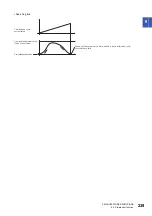
Page 247: ...nsation amount calculated when cam position compensation is requested is divided into the time set in Cam control data No 61 Cam position compensation time constant and used for compensation Control DI 2 bit 13 Cam position compensation target position Cam axis one cycle current value After compensation Before compensation Cam feed current value Control DI 2 bit 13 Status DO 2 bit 13 Cam position ...

Page 248: ... MR Configurator2 Positioning operation jog operation If the servo motor speed changed by the analog override value exceeds the maximum speed of the servo motor the servo motor speed is limited by the maximum speed of the servo motor The servo motor speed can be changed with Override 2DB0h The following table lists the objects related to analog override Use bit 7 of Control DI7 2D07h to select the...

Page 249: ...ions in which digital override cannot be used Test operation mode in MR Configurator2 Positioning operation jog operation If the servo motor speed changed by the digital override value exceeds the maximum speed of the servo motor the servo motor speed is limited by the maximum speed of the servo motor The actual servo motor speed is the result of multiplying the command speed by the digital overri...

Page 250: ... New set point Controlword bit 5 Direction Target point table Power supply ALM Malfunction All turned off All turned off All turned off All turned off Digital override 100 Digital override 85 Station position No 1 Station position No 1 Station position No 3 Forward rotation Servo motor speed Station position No 3 Reverse rotation Digital override 50 Within 3 5 ms Digital override 85 Digital overri...

Page 251: ...e digital override is changed to a value other than 0 the jog operation will start again At this time even if Controlword bit 4 is off the servo motor will stop at the closest station ON OFF ON OFF ON OFF ON OFF 1 2 2 3 4 5 6 7 8 2 1 0 r min Control DI8 bit 3 to bit 6 Status DO5 bit 6 S_MEND Point actual value Controlword bit 4 New set point 8 1 2 Power supply All turned off All turned off Digital...

Page 252: ...election PARAMETERS Symbol Description Pr PA11 TLP Forward rotation torque limit Pr PA12 TLN Reverse rotation torque limit Pr PC77 TL2 Internal torque limit 2 Pr PT11 ZTT Stopper type home position return torque limit value Pr PT48 _ _ _ x TOP7A Torque limit selection during stop CTL and C_CTL Internal torque limit selection Limit value status Enabled torque limit value CCW power running CW regene...

Page 253: ...ion status 1 Limit value status Enabled torque limit value CCW power running CW regeneration CW power running CCW regeneration 0 Disabled All off During a stop Pr PC77 Pr PC77 Operating Pr PA11 Pr PA12 Either one on During a stop Pr PC77 Pr PC77 Operating Pr PA11 Pr PA12 Pr PC77 Pr PC77 1 enabled All off During a stop Pr PA11 Pr PA12 Pr PC77 Pr PC77 Operating Pr PA11 Pr PA12 Either one on During a...

Page 254: ...ed length multiplication STM setting of Pr PT03 EEP ROM Indicates whether data can be stored in the non volatile memory Data cannot be stored in the non volatile memory The value of the data written from the controller returns to the value of Default when the power is shut off Data can be stored in the non volatile memory with Store Parameters 1010h Data is saved in the servo parameter correspondi...

Page 255: ... The values of the basic setting parameters Pr PA_ _ can be obtained and set Refer to chapter 7 for details I32 rw Impossible PA01 to PA32 2081 to 20C0 0 PB01 to PB64 The values of the gain filter setting parameters Pr PB_ _ can be obtained and set Refer to chapter 7 for details I32 rw Impossible PB01 to PB64 2101 to 2150 0 PC01 to PC80 The values of the extension setting parameters Pr PC_ _ can b...

Page 256: ...ation Unit ms U16 rw Impossible 0 00000000h to 00004E20h ms 4 Deceleration Unit ms U16 rw Impossible 0 00000000h to 00004E20h ms 5 Dwell Unit ms U16 rw Impossible 0 00000000h to 00004E20h ms 6 Auxiliary Absolute value command method 0 Automatic operation for a selected point table is performed 1 Automatic operation for the next point table is performed 8 Automatic operation for a point table selec...

Page 257: ...er of the currently occurring alarm is returned When no alarm has occurred 00000000h is returned Bit 0 to Bit 15 Alarm detail number Bit 16 to Bit 31 Alarm number U32 ro Possible 00000000h to FFFFFFFFh 2A42 0 Current alarm 2 The alarm number of the currently occurring alarm is returned When no alarm has occurred 0000h is returned Bit 0 to Bit 7 Alarm detail number Bit 8 to Bit 15 Alarm number U16 ...

Page 258: ...manufacturer setting 09 Parameter for manufacturer setting 0A Parameter for manufacturer setting 0B Pr PL _ _ 0C Pr PT _ _ 0E Pr PN _ _ 0F Parameter for manufacturer setting U16 ro Impossible 0 0000h to FFFFh 2A46 0 Reset alarm Writing the value 1EA5h resets the alarm Any value other than 1EA5h is invalid U16 wo Impossible 0000h to FFFFh 2B01 0 Cumulative feedback pulses The cumulative feedback pu...

Page 259: ...ncoder information 1 Z phase counter The load side encoder information 1 is returned I32 ro Possible 80000000h to 7FFFFFFFh pulse 2B13 0 Load side encoder information 2 The load side encoder information 2 is returned I32 ro Possible 80000000h to 7FFFFFFFh pulse 2B17 0 Temperature of motor thermistor The temperature of motor thermistor is returned I16 ro Possible 8000h to 7FFFh C 2B18 0 Motor side ...

Page 260: ... Droop pulses The droop pulses at alarm occurrence are returned I32 ro Possible 80000000h to 7FFFFFFFh pulse 2B84 0 Alarm Monitor 4 Cumulative command pulses The cumulative command pulses encoder unit at alarm occurrence are returned I32 ro Possible 80000000h to 7FFFFFFFh pulse 2B85 0 Alarm Monitor 5 Command pulse frequency The command pulse frequency at alarm occurrence is returned I32 ro Possibl...

Page 261: ...3 Temperature of motor thermistor The temperature of motor thermistor at alarm occurrence is returned I32 ro Possible 8000h to 7FFFh C 2B98 0 Alarm Monitor 24 Motor side cumu feedback pulses before gear The cumulative feedback pulses servo motor side unit at alarm occurrence are returned I32 ro Possible 80000000h to 7FFFFFFFh pulse 2BA3 0 Alarm Monitor 35 Motor side load side position deviation Th...

Page 262: ...thod the value is fixed to 0 I32 ro Possible 80000000h to 7FFFFFFFh 2BB0 0 Alarm Monitor 48 Command position The command position at alarm occurrence is returned In the indexer method the value is fixed to 0 I32 ro Possible 80000000h to 7FFFFFFFh 2BB1 0 Alarm Monitor 49 Command remaining distance The command remaining distance at alarm occurrence is returned I32 ro Possible 80000000h to 7FFFFFFFh ...

Page 263: ...tion 1 Normal Estimation is completed 2 Warning the servo motor may rotate in one direction too frequently 3 Warning the servo motor speed may be too slow for friction estimation 4 Warning the change in the servo motor speed may be small for friction estimation 5 Warning the acceleration deceleration time constants may be too short for friction estimation 6 Warning the operation time may not be en...

Page 264: ... 1 I16 ro Impossible 0 8000h to 7FFFh 0 1 2C25 0 Oscillation frequency during motor stop Vibration frequency during stop servo lock is returned in increments of 1 Hz I16 ro Impossible 0 8000h to 7FFFh Hz 2C26 0 Vibration level during motor stop The vibration level during stop servo lock is returned in increments of 0 1 I16 ro Impossible 0 8000h to 7FFFh 0 1 2C27 0 Oscillation frequency during moto...

Page 265: ...l travel distance Bits 16 to 31 Reserved U32 ro Impossible 0 00000000h to FFFFFFFFh 2C2A 0 Friction based fault prediction upper Threshold The upper limit threshold used for friction failure prediction is displayed in increments of 0 1 assuming the rated torque as 100 I32 ro Impossible 0 80000000h to 7FFFFFFFh 0 1 2C2B 0 Friction based fault prediction lower Threshold The lower limit threshold use...

Page 266: ...et U32 rw Possible 50000 00000000h to instantaneous permissible speed 0 01 r min 0 01 mm s PT67 2D28 0 Motor rated speed The servo motor rated speed is returned U32 ro Impossible 00000000h to FFFFFFFFh r min mm s 2D30 0 Manufacturer Device Name 2 The number of characters 32 of the model name of the servo amplifier is returned VISIBLE STRING ro Impossible 1 to 32 Manufacturer Device Name 2 The mode...

Page 267: ...e absolute position type or not is returned 0 Incremental type 1 Absolute position type Bit 3 to Bit 31 Reserved U32 ro Impossible 00000000h to 00000111h 2D42 0 Max ABS counter The maximum value of the multi revolution counter is displayed U32 ro Impossible 00000000h to FFFFFFFFh rev 2D43 0 Optional unit identification information The number of digits 16 of the optional unit identification informa...

Page 268: ...hed normally C000 Tuning canceled C001 Overshoot exceeded C002 Servo off during tuning C003 Control mode error C004 Time out C005 Load to motor inertia ratio misestimated C00F One touch tuning disabled U16 ro Impossible 0 0000h to C00Fh 2D60 0 Target point table In the point table mode pt Specify a point table No 0 Not operate 1 to 255 Execute the specified point table 1 High speed home position r...

Page 269: ... Controlword Set control commands to control the servo amplifier Bit 0 switch on Bit 1 enable voltage Bit 2 quick stop Bit 3 enable operation Bit 4 to Bit 6 operation mode specific Bit 7 fault reset Bit 8 halt Bit 9 operation mode specific Bit 10 to Bit 14 reserved Bit 15 operation mode specific U16 rw Possible 0 0000h to FFFFh 6041 0 Statusword The current control status can be checked Bit 0 read...

Page 270: ...d 0 is returned I32 ro Possible 80000000h to 7FFFFFFFh pos units 606B 0 Velocity demand value The speed command is returned I32 ro Possible 0 80000000h to 7FFFFFFFh 0 01 r min 0 01 mm s 606C 0 Velocity actual value The current speed is returned I32 ro Possible 80000000h to 7FFFFFFFh 0 01 r min 0 01 mm s 6072 0 Max torque The maximum torque of the servo motor is returned The value matches with the ...

Page 271: ...ion direction selection can be set Bit 7 position polarity Bit 6 velocity polarity Bit 5 torque polarity Turn on or off both bits 6 and 7 to set the rotation direction to position commands and speed commands Turn on or off all of bits 5 to 7 to set the rotation direction to torque commands U8 rw Possible 00h 00h to FFh PA14 PC29 607F 0 Max profile velocity Set the maximum speed commands in the Jog...

Page 272: ...formed with 100 ms Range Limited within the range of 0 to 20000 When 0 is set the operation is performed with 100 ms The operation depends on the specification of Pr PC51 U32 rw Possible 100 00000000h to FFFFFFFFh ms PC24 608F 0 Position encoder resolution The number of entries is returned U8 ro Impossible 2 02h fixed pulse rev 1 Encoder increments The encoder resolution is returned U32 rw Possibl...

Page 273: ...instantaneous permissible speed 0 01 r min PT05 2 Speed during search for zero Set a creep speed after proximity dog at home position return U32 rw Possible 1000 0 to instantaneous permissible speed 0 01 r min PT06 609A 0 Homing acceleration Set the acceleration deceleration time constants at home position return Set a time for the servo motor to reach the rated speed U32 rw Possible 0 00000000h t...

Page 274: ...in increments of 0 1 U16 rw Possible 10000 0000h to 2710h 10000 0 1 PA12 PA11 60E3 0 Supported homing method The number of supported homing methods is returned U8 ro Impossible 38 00h to FFh 1 to 38 1st supported homing method Set the number of the supported home position return type I8 ro Impossible 37 80h to 7Fh 60F2 0 Positioning option code Set the positioning operation pattern U16 rw Possible...

Page 275: ...g sub object of Store parameters 1010h to save the object in the EEP ROM of the servo amplifier The value saved in the EEP ROM is set to the object at the next power on Servo parameters can also be modified through the object dictionary However the new setting is not automatically written to the EEP ROM To write the new setting use Store parameters 1010h Executing Store parameters 1010h takes abou...

Page 276: ...or Restore default parameters 1011h The servo amplifier parameters can be rewritten to the factory setting Write 64616F6Ch reverse order of ASCII code of load to Restore all default parameters 1011h 1 and then cycle the power to initialize the parameters Sub Index Item Saved parameter Returned value 0 Number of entries 04h 1 Save all parameters Index 2001h to 27FFh 00000001h available 2 For manufa...

Page 277: ...0h 1 to Mapped Object 032 1A00h 32 are as follows Page 25 Link device Usage Follow the procedure below to change the response message mapping Index Sub Index Name Data Type Access 1A00h 0 Transmit PDO Mapping Number of entries U8 rw 1 Mapped Object 001 U32 32 Mapped Object 032 Name Bit Description Transmit PDO Mapping 001 to 032 16 to 31 Index of objects to be mapped 8 to 15 Sub Index of objects t...

Page 278: ... Index 1 to 32 regardless of object size The required number of RWr is secured automatically Ensure that total size of the objects to be mapped is 64 bytes or less A gap can be inserted by setting Index 0 and Sub Index 0 for the object to be mapped Set the gap size in bits for the size of the object to be mapped Placement changed in the response message mapping is not saved Set the placement again...

Page 279: ...to 999999 1 Incremental value command method 00000000h to 000F423Fh 0 to 999999 1 inch 0 Absolute value command method FFF0BDC1h to 000F423Fh 999999 to 999999 1 Incremental value command method 00000000h to 000F423Fh 0 to 999999 2 degree 0 Absolute value command method FFFA81C0h to 00057E40h 360000 to 360000 1 Incremental value command method 00000000 to 000F423Fh 0 to 999999 3 pulse 0 Absolute va...

Page 280: ...n time constant error 4 0 No error 1 Deceleration time constant error 5 0 No error 1 Dwell error 6 0 No error 1 Auxiliary function error 7 to 31 reserved Index Sub Index Name Data Type Access 2D01h to 2D0Ah 0 Control DI1 to Control DI10 U16 rw Bit Symbol Description 0 The value at reading is undefined Set 0 when writing 1 2 3 4 C_CDP Gain switching Turning C_CDP on switches the values of Pr PB29 t...
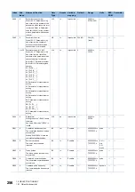
Page 281: ...que less than the rated torque 9 The value at reading is undefined Set 0 when writing 10 11 C_CLTC Clutch command This is used to turning on off the main shaft clutch command This is used when Cam control data No 36 Main shaft clutch control setting is set to _ _ _ 1 12 The value at reading is undefined Set 0 when writing 13 C_CPCD Cam position compensation request Turn C_CPCD on to compensate the...

Page 282: ... of control DI5 Bit Symbol Description 0 The value at reading is undefined Set 0 when writing 1 2 3 4 5 6 7 8 9 10 11 12 13 14 15 Bit Symbol Description 0 The value at reading is undefined Set 0 when writing 1 2 3 4 5 6 7 8 9 10 11 C_DOG Proximity dog input 12 The value at reading is undefined Set 0 when writing 13 14 15 ...

Page 283: ... servo amplifiers with software version A6 or later Bit Symbol Description 0 The value at reading is undefined Set 0 when writing 1 2 3 4 5 6 7 8 9 10 11 12 13 14 15 Bit Symbol Description 0 The value at reading is undefined Set 0 when writing 1 2 3 4 5 6 7 C_OVR 1 Analog override selection 8 The value at reading is undefined Set 0 when writing 9 10 11 12 13 14 15 ...

Page 284: ...bol Description 0 The value at reading is undefined Set 0 when writing 1 2 3 C_OV0 1 Digital override selection 1 4 C_OV1 1 Digital override selection 2 5 C_OV2 1 Digital override selection 3 6 C_OV3 1 Digital override selection 4 7 The value at reading is undefined Set 0 when writing 8 9 10 11 12 13 14 15 Bit Symbol Description 0 The value at reading is undefined Set 0 when writing 1 2 3 4 5 6 7 ...

Page 285: ... on 3 S_MBR Electromagnetic brake interlock When a servo off status or alarm occurs S_MBR turns off 4 S_CDPS Variable gain selection S_CDPS turns on during variable gain 5 S_CLD During fully closed loop control switching S_CLD turns on during fully closed loop control 6 The value at reading is undefined 7 8 9 10 11 12 S_INP In position When the number of droop pulses is in the in position range S_...

Page 286: ...when the clutch is off and the smoothing is completed 13 S_CPCC Cam position compensation execution completed It outputs clutch smoothing status The output depends on the setting in Cam control data No 42 Main shaft clutch smoothing system as follows 0 Direct Always off 1 Time constant system Exponent Always on in clutch on status It turns off when the clutch is off and the smoothing is completed ...
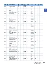
Page 287: ...e value at reading is undefined 1 2 3 4 5 S_STO During STO S_STO turns on during STO 6 The value at reading is undefined 7 8 9 10 11 S_MTTR During tough drive 12 The value at reading is undefined 13 14 15 Bit Symbol Description 0 The value at reading is undefined 1 2 3 4 5 6 7 8 9 10 11 12 13 14 S_PRMWR 1 Parameter enable wait When a parameter is changed S_PRMWR turns on if there is a disabled par...

Page 288: ...re within the in position output range set with Pr PA10 and the command remaining distance is 0 S_MEND turns on S_MEND turns on with servo on S_MEND is off at servo off status However S_MEND does not turn off in the indexer method even at servo off status 7 The value at reading is undefined 8 S_PUS 1 When a deceleration begins for a stop while Halt Temporary stop restart is on S_PUS turns on When ...

Page 289: ...reading is undefined 1 2 S_POT 1 Position range When the current position is within the range set with Pr PT19 to Pr PT22 S_POT turns on This will be off when a home position return is not completed or base circuit shut off is in progress This bit can be used only with the point table method 3 The value at reading is undefined 4 5 6 7 8 9 10 11 12 13 14 15 Bit Symbol Description 0 The value at rea...

Page 290: ...s in the 2000s Bit definition of status DO9 Bit definition of status DO10 Bit Symbol Description 0 The value at reading is undefined 1 2 3 4 5 6 7 8 9 10 11 12 13 14 15 Bit Symbol Description 0 The value at reading is undefined 1 2 3 4 5 6 7 8 9 10 11 12 13 14 15 ...

Page 291: ... Index Name Data Type Access 2D60h 0 Target Point Table I16 rw Control mode Setting value Point table mode pt 0 Not operate 1 to 255 Execute the specified point table 1 High speed home position return Indexer mode idx 0 to 254 Positioning operation to specified stations Index Sub Index Name Data Type Access 2D68h 0 Point Demand Value I16 ro Pr PA01 Control mode Setting value _ _ _ 0 Point table mo...

Page 292: ...can be read This is available with servo amplifiers with software version A7 or later Usage Use this object to read the software version of the servo amplifier ASCII 3 characters If it is less than 3 characters it will be padded with spaces 20h As an example in the case of software version A7 when SDO Object SubID Block Upload is used and Sub Index 1 and Number of data value 0 up to the final Sub ...

Page 293: ...he serial No of the servo motor ASCII 16 characters If it is less than 16 characters it will be padded with NUL 00h When the serial number cannot be read NUL 00h is read As an example if the serial No is 123456789 when SDO Object SubID Block Upload is used and Sub Index 1 and Number of data value 0 up to the final Sub Index are specified the serial No is read as follows Index Sub Index Name Data T...

Page 294: ...tion code 605Dh Control mode display 6061h The current control mode can be read The setting value of each control mode is as follows Index Sub Index Name Data Type Access 605Ah 0 Quick stop option code I16 rw Setting value Description 1 For manufacturer setting 2 In the homing mode hm point table mode pt Jog mode jg and indexer mode idx the servo motor decelerates to a stop with Quick stop deceler...

Page 295: ...t 607Dh function is disabled Polarity 607Eh The rotation direction selection can be set The rotation direction of a servo motor to position commands speed commands and torque commands can be set To set the rotation direction to position commands and speed commands turn on or off both bits 6 and 7 of Polarity 607Eh or use Pr PA14 To set the rotation direction to torque commands turn on or off all o...

Page 296: ...l mode Pr PT01 and Pr PT03 Index Sub Index Name Data Type Access 6092h 0 Feed constant Feed constant U8 ro 1 Feed U32 rw 2 Shaft revolutions U32 rw Control mode Pr PT01 setting Pr PT03 setting Range Feed Shaft revolutions Point table method _ 0 _ _ mm _ 1 _ _ inch _ _ _ 0 Encoder resolution of the servo motor 1 _ _ _ 1 10 _ _ _ 2 100 _ _ _ 3 1000 _ 2 _ _ degree _ _ _ 0 to _ _ _ 3 360000 1 _ 3 _ _ ...
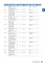
Page 297: ...h Touch probe pos1 pos value 60BAh and Touch probe pos1 neg value 60BBh The following shows the touch probe detection resolution Enabling the high precision touch probe disables the encoder output pulses For details of each object refer to sections 10 4 9 to 10 4 14 Index Sub Index Name Data Type Access 60B8h 0 Touch probe function U16 rw 60B9h 0 Touch probe status U16 ro 60BAh 0 Touch probe pos1 ...

Page 298: ...PR1 Touch probe 1 turns off is not stored as the Touch probe position negative value 60BBh f 7 Latching can be done continuously from c g The following shows a timing chart High precision touch probe TPR2 touch probe 2 supports high precision touch probe The normal touch probe has the latch function with precision of 55 s On the other hand the high precision touch probe latches precisely startup o...

Page 299: ...op sampling at the rising edge of touch probe 1 1 Start sampling at the rising edge of touch probe 1 When the input of touch probe 1 is set as a trigger Bit 2 0 the position feedback latched at rising edge of touch probe 1 is stored in Touch probe pos1 pos value 60BAh 5 0 Stop sampling at the falling edge of touch probe 1 1 Start sampling at the falling edge of touch probe 1 When the input of touc...

Page 300: ...not been stored 1 The rising edge position of touch probe 1 has been stored When the position feedback is stored in Touch probe pos1 pos value 60BAh this bit becomes 1 When 0 is set in the bit 4 of Touch probe function 60B8h this bit becomes 0 2 0 The falling edge position of touch probe 1 has not been stored 1 The falling edge position of touch probe 1 has been stored When the position feedback i...

Page 301: ...value 60BCh The current rising edge position of touch probe 2 can be checked Touch probe pos2 neg value 60BDh The current falling edge position of touch probe 2 can be checked Index Sub Index Name Data Type Access 60BAh 0 Touch probe pos1 pos value I32 ro Index Sub Index Name Data Type Access 60BBh 0 Touch probe pos1 neg value I32 ro Index Sub Index Name Data Type Access 60BCh 0 Touch probe pos2 p...

Page 302: ... clamped within the range of 0 to 359 999 Touch probe pos1 pos value 60BAh 0 The range changes to 0 to 359 999 Touch probe pos1 neg value 60BBh 0 The range changes to 0 to 359 999 Touch probe pos2 pos value 60BCh 0 The range changes to 0 to 359 999 Touch probe pos2 neg value 60BDh 0 The range changes to 0 to 359 999 Home offset 607Ch 0 The range changes to 0 to 359 999 Current position 2B2Fh 0 The...

Page 303: ...ates in only the address decreasing direction Bit 7 1 Bit 6 0 Rotates in only the address increasing direction Bit 7 1 Bit 6 1 Rotates in the shorter direction Bit 7 0 Bit 6 0 Rotates in the direction specified with the sign of the position data Bit 7 0 Bit 6 1 Rotates in only the address decreasing direction Bit 7 1 Bit 6 0 Rotates in only the address increasing direction Bit 7 1 Bit 6 1 Rotates ...

Page 304: ...ction 6 1 Partially added and partially changed Section 6 2 Partially added and partially changed Section 6 3 Partially added and partially changed Section 6 4 Partially changed Section 7 1 Partially added and partially changed Section 7 2 Partially added and partially changed Section 9 1 The whole section is changed Section 9 5 Partially changed Section 9 6 Newly added Section 9 7 Newly added Cha...

Page 305: ...ou acknowledge we are not responsible for 2 Term of warranty after the stop of production 1 We may accept the repair at charge for another seven 7 years after the production of the product is discontinued The announcement of the stop of production for each model can be seen in our Sales and Service etc 2 Please note that the Product including its spare parts cannot be ordered after its stop of pro...

Page 306: ...rademarks of Mitsubishi Electric Corporation in Japan and or other countries Ethernet is a registered trademark of Fuji Xerox Co Ltd in Japan All other product names and company names are trademarks or registered trademarks of their respective companies SH NA 030273ENG B ...

Page 307: ......

Page 308: ...tice When exported from Japan this manual does not require application to the Ministry of Economy Trade and Industry for service transaction permission HEAD OFFICE TOKYO BUILDING 2 7 3 MARUNOUCHI CHIYODA KU TOKYO 100 8310 JAPAN NAGOYA WORKS 1 14 YADA MINAMI 5 CHOME HIGASHI KU NAGOYA JAPAN ...

Reviews: