9 MANUFACTURER FUNCTIONS
9.5 Simple cam function
231
9
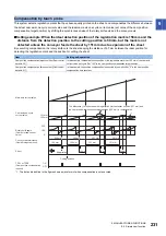
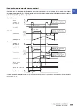
Compensation by touch probe
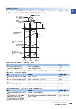
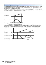
This system detects registration marks that have been equally printed on the sheet, and compensates the difference between
the actual cam axis one cycle current value and the ideal cam axis one cycle current value (set value of the cam position
compensation target position) by shifting the synchronous phase of the rotary knife axis and the conveyor axis.
■
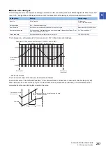
Setting example: When the ideal detection position of the registration mark is 150 mm and the
distance from the detection position to the cutting position is 50 mm, but the mark is not
detected unless the conveyor feeds the sheet by 151 mm due to expansion of the sheet
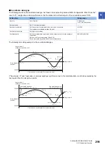
By executing compensation, the rotary knife cuts the sheet keeping the distance of 50 mm between the ideal position for
detecting the registration mark and the position for cutting the sheet.
*1 The dot-and-dash line in the figure shows a waveform of when compensation is not executed.
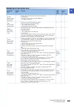
Item
Setting and operation
Cam position compensation target position ([Cam control
data No. 60])
In this example, the ideal detection position of the registration mark is at 150 mm of the cam axis
current value per cycle. Set "150" in the cam position compensation target position.
Cam position compensation time constant ([Cam control
data No. 61])
In this example, the position compensation is executed by one-shot. Set "0" in the cam position
compensation time constant.
360°
180°
0°
151 mm
150 mm
ON
OFF
150 mm
150 mm
151 mm
151 mm
50 mm
201 mm
201 mm
200 mm
200 mm
50 mm
50 mm
*1
Main axis current value
The difference (1 mm) between the registration mark detection position (151 mm) and
the cam position compensation target position (150 mm) is compensated.
Cam axis one cycle
current value
Rotary knife angle
(Cam axis feed current
value)
Conveyor travel distance
(Cam axis input amount)
Sheet
Registration
mark
Cutting position
TPR1 or TPR2
(Cam position compensation
request)

