228
9 MANUFACTURER FUNCTIONS
9.5 Simple cam function
Operation
• Execute operation so that the machine speed of the input axis is equal to or less than "[Cam control data
No. 48 - Cam axis length per cycle] × 1/2 × 1000 [command unit/s]". Failure to do so may cause the input
axis and output axis to become out of synchronization.
A rotary knife system is shown as an example of the operation of the simple cam function.
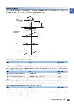
Configuration example
The rotary knife cuts the sheet conveyed by the conveyor at a constant speed into a desired length.
The cutting positions are compensated based on detection of the registration marks printed on the sheet to prevent variations
in the sheet length and deviations in cutting position.
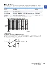
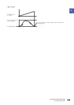
*1 Set the machine speed of the input axis to a value that satisfies the following equation.
Machine speed
≤
[Cam control data No. 48 - Cam axis length per cycle] × 1/2 × 1000 [command unit/s]
To check the machine speed, monitor the main axis current value with the graph function of MR Configurator2.
The machine speed is calculated as follows:
Machine speed = (L2 - L1)/(T2 - T1)
MR-J4-GF-RJ
Servo amplifier
A/B-phase output
Touch probe
Machine
speed
*1
Rotary knife axis
Synchronous encoder
Servo motor for driving the cam axis
Conveyor axis
Drives the conveyor using an inverter or
other servo amplifier
T2
T1
L1
L2
Main axis current value
Time


