

16 - 24
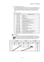
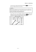
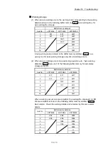
Chapter 16 Troubleshooting
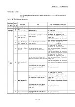
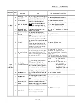
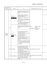
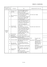
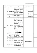
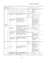
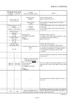
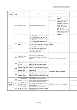
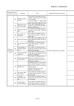
Classification
of errors
Error
code
Error name
Error
Operation status at error occurrence
Positioning
operation
errors
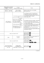
504
Outside linear
movement amount
range
• When the parameter "interpolation speed
designation method" performs a linear
interpolation in setting a "composite
speed", the axis movement amount for
each positioning data exceeds
1073741824(2
30
).
• The positioning address is
–360.00000 or less or 360.00000 or more
using INC instruction, where the control
unit is set to "degree" and software stroke
limit upper limit is not equal to the
software stroke limit lower limit.
At start
: The system does not
operate.
During operation : The system stops
immediately.
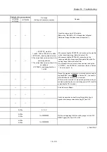
506
Large arc error
deviation
When an arc is interpolated by the
designation of the center point, a difference
between a radius of start point-center point
and a radius of end point-center point
exceeds the parameter "Circular
interpolation error allowable limit".
At start
: The circular interpolation
control by center point
designation is not
executed.
During operation : The system stops
immediately.
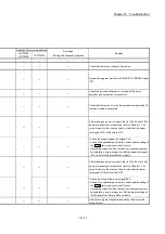
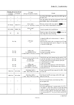
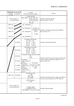
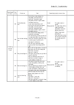
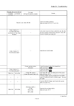
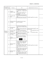
507 Software stroke limit+
• The positioning is executed at a position
exceeding the upper limit of the software
stroke limit.
• The positioning address and the new
current value exceed the upper limit of the
software stroke limit.
• In the circular interpolation with sub points
designated, the sub point exceeds the
upper limit of the software stroke limit.
• During the speed control mode/the torque
control mode/the continuous operation to
torque control mode, the current feed
value exceeded the upper limit of the
software stroke limit.
At operation start:
The system does not operate.
In the analysis of new current value:
Current value is not changed.
During operation:
• The system stops immediately
when the positioning address during
position control (including position
control in speed-position switching
control or position-speed switching
control) is switched to the data
outside the software stroke limit
range.
• During speed control (including
speed control in speed-position
switching control or position-speed
switching control), the system stops
at the setting (normal deceleration
stop only) of sudden stop selection
(stop group 3) in the detailed
parameter 2 when the current feed
value or machine feed value during
manual control is outside the
software stroke limit range.
At speed control mode/torque control mode/
continuous operation to torque control mode:
The system switches to the position
control mode and stops immediately
when the current feed value is
outside the software stroke limit
range.
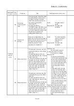
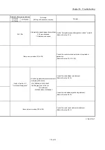
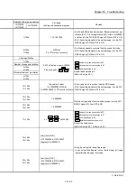
508 Software stroke limit–
• The positioning is executed at a position
exceeding the lower limit of the software
stroke limit.
• The positioning address and the new
current value exceed the lower limit of the
software stroke limit.
• In the circular interpolation with sub points
designated, the sub point exceeds the
lower limit of the software stroke limit.
• During the speed control mode/the torque
control mode/the continuous operation to
torque control mode, the current feed
value exceeded the lower limit of the
software stroke limit.
Summary of Contents for MELSEC-L Series
Page 2: ......
Page 30: ...MEMO ...
Page 70: ...2 10 Chapter 2 System Configuration MEMO ...
Page 83: ...3 13 Chapter 3 Specifications and Functions MEMO ...
Page 103: ...3 33 Chapter 3 Specifications and Functions MEMO ...
Page 107: ...3 37 Chapter 3 Specifications and Functions MEMO ...
Page 111: ...3 41 Chapter 3 Specifications and Functions MEMO ...
Page 115: ...3 45 Chapter 3 Specifications and Functions MEMO ...
Page 140: ...4 22 Chapter 4 Installation Wiring and Maintenance of the Product MEMO ...
Page 253: ...5 113 Chapter 5 Data Used for Positioning Control MEMO ...
Page 342: ...5 202 Chapter 5 Data Used for Positioning Control MEMO ...
Page 438: ...7 20 Chapter 7 Memory Configuration and Data Process MEMO ...
Page 440: ...MEMO ...
Page 485: ...9 25 Chapter 9 Major Positioning Control MEMO ...
Page 594: ...9 134 Chapter 9 Major Positioning Control MEMO ...
Page 624: ...10 30 Chapter 10 High Level Positioning Control MEMO ...
Page 656: ...11 32 Chapter 11 Manual Control MEMO ...
Page 690: ...12 34 Chapter 12 Expansion Control MEMO ...
Page 798: ...13 108 Chapter 13 Control Sub Functions MEMO ...
Page 866: ...14 68 Chapter 14 Common Functions MEMO ...
Page 884: ...15 18 Chapter 15 Dedicated Instructions MEMO ...
Page 899: ...16 15 Chapter 16 Troubleshooting MEMO ...
Page 1036: ...Appendix 88 Appendices MEMO ...
Page 1039: ......


