


10 - 28
Chapter 10 High-Level Positioning Control
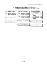
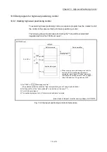
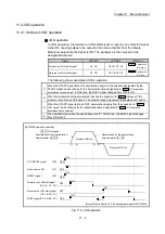
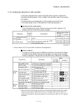
Start time chart
The following chart shows a time chart in which the positioning data No. 1, 2, 10,
11, and 12 of LD77MS4 [axis 1] are continuously executed as an example.
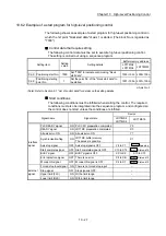
(1) Block start data setting example
Axis 1 block
start data
Da.11
Shape
Da.12
Start data No.
Da.13
Special start
instruction
Da.14
Parameter
1st point
1: Continue
1
0: Block start
–
2nd point
0: End
10
0: Block start
–
(2) Positioning data setting example
Axis 1 positioning
data No.
Da.1
Operation pattern
1
11: Continuous path control
2 00:
Positioning
complete
10
11: Continuous path control
11
11: Continuous path control
12 00:
Positioning
complete
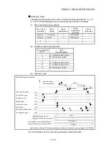
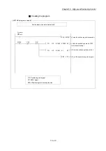
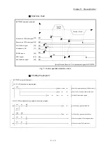
(3) Start time chart
[LD77MS4 operation example]
[Y10]
PLC READY signal
READY signal
[X10]
[XC]
Positioning complete signal
V
t
Error detection signal
Positioning data No.
Dwell time
12(00)
Operation pattern
1(11)
1st point [buffer memory address 26000]
2nd point [buffer memory address 26001]
11(11)
10(11)
2(00)
7000
1
-32767
10
(8001
H
)
(000A
H
)
Cd.3 Positioning start No.
Cd.4 Positioning starting point No.
Positioning start signal
[X0]
Start complete signal
BUSY signal
[X8]
[X14]
[Y0]
All axis servo ON
[Y1]
Dwell time
(Note): Refer to Section 3.3 for input/output signal or Chapter 5 for buffer memory address of LD77MS16.
Fig. 10.3 Start time chart for high-level positioning control (block start)
Summary of Contents for MELSEC-L Series
Page 2: ......
Page 30: ...MEMO ...
Page 70: ...2 10 Chapter 2 System Configuration MEMO ...
Page 83: ...3 13 Chapter 3 Specifications and Functions MEMO ...
Page 103: ...3 33 Chapter 3 Specifications and Functions MEMO ...
Page 107: ...3 37 Chapter 3 Specifications and Functions MEMO ...
Page 111: ...3 41 Chapter 3 Specifications and Functions MEMO ...
Page 115: ...3 45 Chapter 3 Specifications and Functions MEMO ...
Page 140: ...4 22 Chapter 4 Installation Wiring and Maintenance of the Product MEMO ...
Page 253: ...5 113 Chapter 5 Data Used for Positioning Control MEMO ...
Page 342: ...5 202 Chapter 5 Data Used for Positioning Control MEMO ...
Page 438: ...7 20 Chapter 7 Memory Configuration and Data Process MEMO ...
Page 440: ...MEMO ...
Page 485: ...9 25 Chapter 9 Major Positioning Control MEMO ...
Page 594: ...9 134 Chapter 9 Major Positioning Control MEMO ...
Page 624: ...10 30 Chapter 10 High Level Positioning Control MEMO ...
Page 656: ...11 32 Chapter 11 Manual Control MEMO ...
Page 690: ...12 34 Chapter 12 Expansion Control MEMO ...
Page 798: ...13 108 Chapter 13 Control Sub Functions MEMO ...
Page 866: ...14 68 Chapter 14 Common Functions MEMO ...
Page 884: ...15 18 Chapter 15 Dedicated Instructions MEMO ...
Page 899: ...16 15 Chapter 16 Troubleshooting MEMO ...
Page 1036: ...Appendix 88 Appendices MEMO ...
Page 1039: ......


