
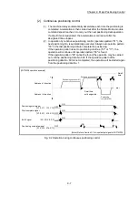


8 - 20
Chapter 8 OPR Control
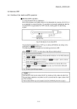
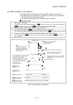
8.4 Selection of the OPR setting condition
8.4.1 Outline of the OPR setting condition
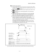
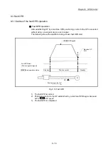
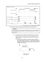
If executing the home position return (OPR) when selecting "0: Need to pass servo
motor Z-phase after power on" with the servo parameter of the servo amplifier
"Function selection C-4 (PC17)", it is necessary that the servomotor has been rotated
more than one revolution and passed the Z phase (Motor reference position signal)
and that the zero point pass signal (
Md.108
Servo status (low-order buffer memory
address): b0) has turned ON.
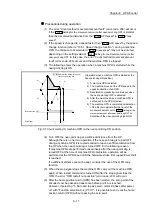
When selecting "1: Not need to pass servo motor Z-phase after power on" with
"Function selection C-4 (PC17)", it is possible to turn the zero point pass signal
(
Md.108
Servo status (low-order buffer memory address): b0) ON without passing the
zero point.
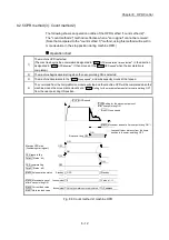
Buffer memory address (low-order)
LD77MS2/ LD77MS4
LD77MS16
Md.108
Servo status: b0
876+100n 2476+100n
n: Axis No.-1
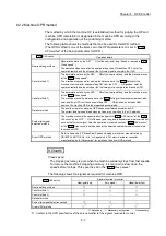
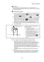
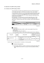
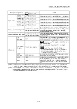
Data setting
To select the "OPR setting condition", set the "servo amplifier" shown in the
following table.
Servo parameters are set for each axis.
The "OPR setting condition" is stored into the following buffer memory addresses.
Setting item
Setting
value
Setting details
Buffer memory address
LD77MS2
LD77MS4
LD77MS16
Function selection C-4
(PC17)
0
0 : Need to pass servo motor Z-phase after
power on
1 : Not need to pass servo motor Z-phase
after power on
30180+200n 28480+100n
n: Axis No.-1
: Refer to Section 5.2.8 "Servo parameters" for information on the storage details.
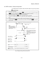
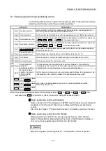
Precautions during operation
(1) Set "Function selection C-4 (PC17)", and then turn off the power supply of the
servo amplifier once and switch it on again to make that parameter setting
valid.
Summary of Contents for MELSEC-L Series
Page 2: ......
Page 30: ...MEMO ...
Page 70: ...2 10 Chapter 2 System Configuration MEMO ...
Page 83: ...3 13 Chapter 3 Specifications and Functions MEMO ...
Page 103: ...3 33 Chapter 3 Specifications and Functions MEMO ...
Page 107: ...3 37 Chapter 3 Specifications and Functions MEMO ...
Page 111: ...3 41 Chapter 3 Specifications and Functions MEMO ...
Page 115: ...3 45 Chapter 3 Specifications and Functions MEMO ...
Page 140: ...4 22 Chapter 4 Installation Wiring and Maintenance of the Product MEMO ...
Page 253: ...5 113 Chapter 5 Data Used for Positioning Control MEMO ...
Page 342: ...5 202 Chapter 5 Data Used for Positioning Control MEMO ...
Page 438: ...7 20 Chapter 7 Memory Configuration and Data Process MEMO ...
Page 440: ...MEMO ...
Page 485: ...9 25 Chapter 9 Major Positioning Control MEMO ...
Page 594: ...9 134 Chapter 9 Major Positioning Control MEMO ...
Page 624: ...10 30 Chapter 10 High Level Positioning Control MEMO ...
Page 656: ...11 32 Chapter 11 Manual Control MEMO ...
Page 690: ...12 34 Chapter 12 Expansion Control MEMO ...
Page 798: ...13 108 Chapter 13 Control Sub Functions MEMO ...
Page 866: ...14 68 Chapter 14 Common Functions MEMO ...
Page 884: ...15 18 Chapter 15 Dedicated Instructions MEMO ...
Page 899: ...16 15 Chapter 16 Troubleshooting MEMO ...
Page 1036: ...Appendix 88 Appendices MEMO ...
Page 1039: ......


