


15- 16
Chapter 15 Dedicated Instructions
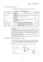
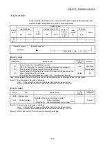
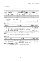
[Functions]
(1) This dedicated instruction is used to return the setting data set in the buffer
memory of Simple Motion module and flash ROM to their factory-set data (initial
values).
Refer to Section 14.2 for initialized setting data.
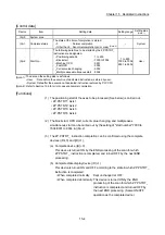
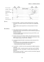
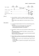
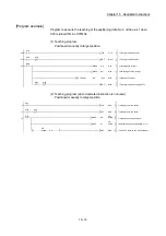
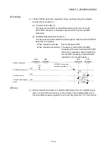
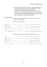
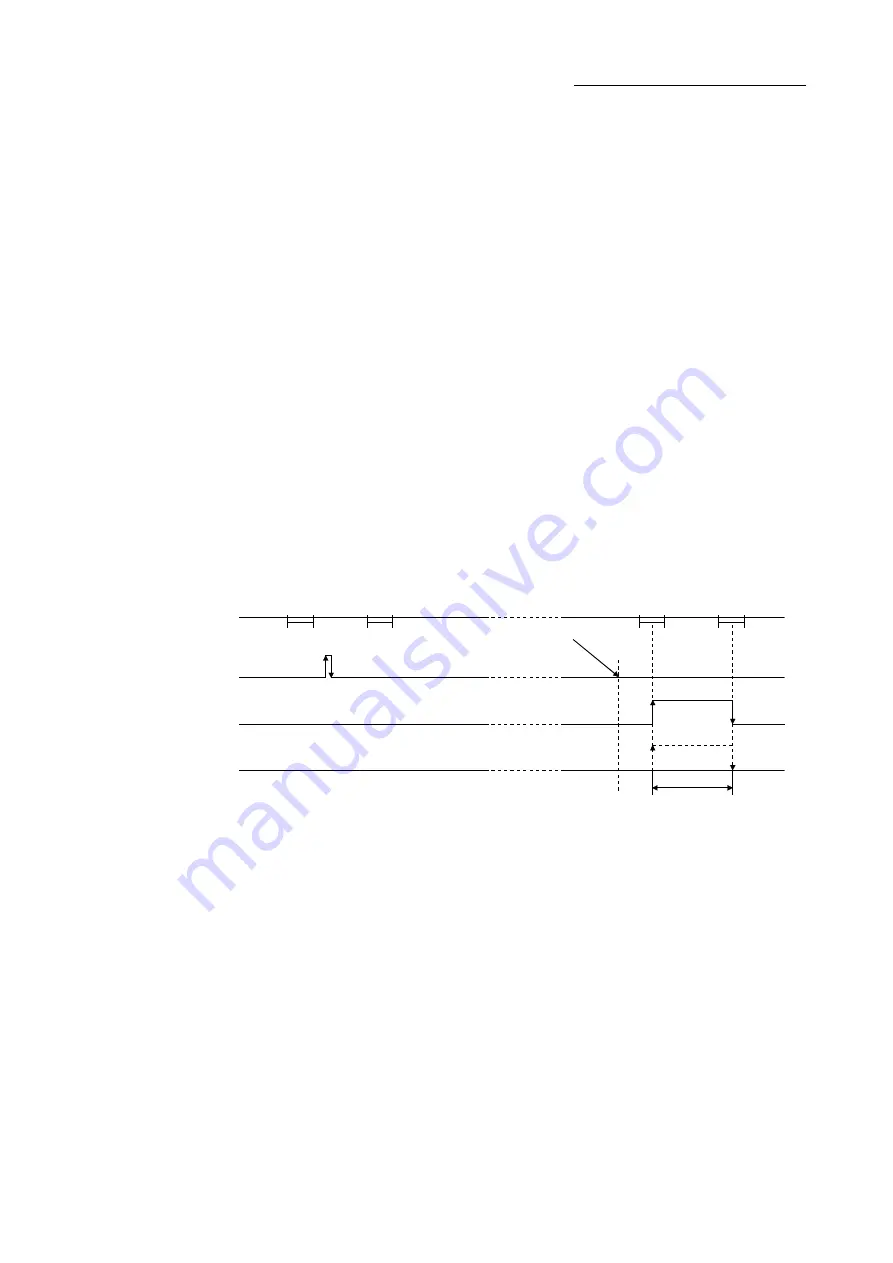
(2) The ZP.PINIT instruction completion can be confirmed using the complete devices
((D)+0) and ((D)+1).
(a) Complete device ((D)+0)
This device is turned ON by the END processing of the scan for which
ZP.PINIT instruction is completed, and turned OFF by the next END
processing.
(b) Complete state display device ((D)+1)
This device is turned ON and OFF according to the state in which ZP.PINIT
instruction is completed.
• When completed normally : Kept unchanged at OFF.
• When completed abnormally : This device is turned ON by the END
processing of the scan for which ZP.PINIT
instruction is completed, and turned OFF by
the next END processing. (Same ON/OFF
operation as the complete device.)
END
processing
END
processing
END
processing
END
processing
OFF
OFF
OFF
ON
ON
ON
When
completed
abnormally
When
completed normally
1 scan
ZP.PINIT instruction
execution completion
Sequence program
ZP.PINIT instruction
Complete device
Complete state display
device
[Errors]
(1) When a dedicated instruction is completed abnormally, the error complete signal
((D)+1) is turned ON, and the error code is stored in the complete status ((S)+1).
Check and take measures against the error referring to Section 16.5 "List of errors".
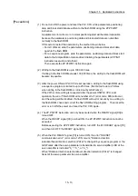
[Precautions]
(1) The ZP.PINIT instruction can only be executed when the READY signal [X0] is
turned OFF.
When the READY signal [X0] is turned ON, the ZP.PINIT instruction cannot be
executed.
Before executing the ZP.PINIT instruction, turn OFF the PLC READY signal [Y0]
and then turn OFF the READY signal [X0].
(2) Writing to the flash ROM is up to 100,000 times.
If writing to the flash ROM exceeds 100,000 times, the writing to the flash ROM will
become impossible.
Summary of Contents for MELSEC-L Series
Page 2: ......
Page 30: ...MEMO ...
Page 70: ...2 10 Chapter 2 System Configuration MEMO ...
Page 83: ...3 13 Chapter 3 Specifications and Functions MEMO ...
Page 103: ...3 33 Chapter 3 Specifications and Functions MEMO ...
Page 107: ...3 37 Chapter 3 Specifications and Functions MEMO ...
Page 111: ...3 41 Chapter 3 Specifications and Functions MEMO ...
Page 115: ...3 45 Chapter 3 Specifications and Functions MEMO ...
Page 140: ...4 22 Chapter 4 Installation Wiring and Maintenance of the Product MEMO ...
Page 253: ...5 113 Chapter 5 Data Used for Positioning Control MEMO ...
Page 342: ...5 202 Chapter 5 Data Used for Positioning Control MEMO ...
Page 438: ...7 20 Chapter 7 Memory Configuration and Data Process MEMO ...
Page 440: ...MEMO ...
Page 485: ...9 25 Chapter 9 Major Positioning Control MEMO ...
Page 594: ...9 134 Chapter 9 Major Positioning Control MEMO ...
Page 624: ...10 30 Chapter 10 High Level Positioning Control MEMO ...
Page 656: ...11 32 Chapter 11 Manual Control MEMO ...
Page 690: ...12 34 Chapter 12 Expansion Control MEMO ...
Page 798: ...13 108 Chapter 13 Control Sub Functions MEMO ...
Page 866: ...14 68 Chapter 14 Common Functions MEMO ...
Page 884: ...15 18 Chapter 15 Dedicated Instructions MEMO ...
Page 899: ...16 15 Chapter 16 Troubleshooting MEMO ...
Page 1036: ...Appendix 88 Appendices MEMO ...
Page 1039: ......


