


5 - 70
Chapter 5 Data Used for Positioning Control
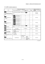
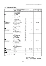
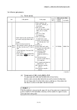
5.2.8 Servo parameters
(1) Servo series
Item
Setting details
Setting range
Default
value
Buffer memory address
LD77MS2
LD77MS4
LD77MS16
Pr.100
Servo
series
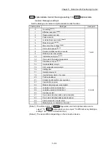
Used to select the servo amplifier series
to connect to the Simple Motion module.
POINT
• Be sure to set up servo series.
Communication with servo amplifier isn't
started by the initial value "0" in default
value.
(The LED indication of servo amplifier
indicates "Ab".)
• The connectable servo amplifier differs
by the setting of "
Pr.97
SSCNET setting
".
0: Servo series is not set
1: MR-J3-_B_, MR-J3W-_B
(2-axis type)
3: MR-J3-_B_-RJ006
(For fully closed loop control)
MR-J3-_BS_ (For safety
servo)
4: MR-J3-_B_-RJ004
(For linear servo)
6: MR-J3-_B-RJ080W
(For direct drive motor)
32: MR-J4-_B_(-RJ), MR-J4W_-
_B (2-axis type and 3-axis
type)
48: MR-JE-_B
64: FR-A700 series (Inverter)
96: VCII series (manufactured by
Nikki Denso Co., Ltd.)
97: AlphaStep/5-Phase
(manufactured by
ORIENTAL MOTOR Co.,
Ltd.)
98: IAI electric actuator
controller (manufactured by
IAI Corporation)
99: VPH series (manufactured by
Nikki Denso Co., Ltd.)
4097: Virtual servo amplifier
(MR-J3)
4128: Virtual servo amplifier
(MR-J4)
0 30100+200n
28400+100n
n: Axis No. -1
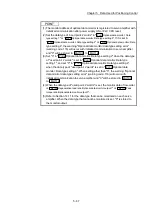
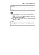
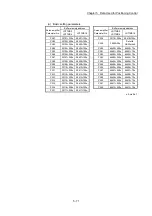
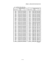
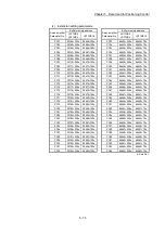
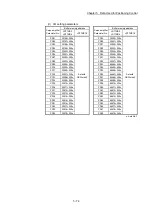
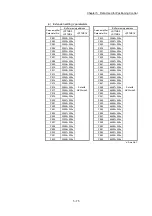
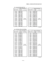
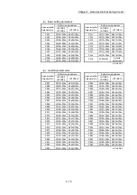
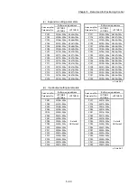
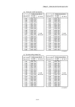
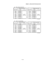
(2) Parameters of MR-J4(W)-B/MR-JE-B
The parameter list for MR-J4(W)-B/MR-JE-B is shown below.
Refer to each servo amplifier instruction manual for details of setting items.
Do not change other than the buffer memory addresses of the parameters
described in each servo amplifier instruction manual.
POINT
Set the parameter value and switch power off once (The parameter is transferred to
servo amplifier from Simple Motion module), and then switch it on again to make
that parameter setting valid.
Summary of Contents for MELSEC-L Series
Page 2: ......
Page 30: ...MEMO ...
Page 70: ...2 10 Chapter 2 System Configuration MEMO ...
Page 83: ...3 13 Chapter 3 Specifications and Functions MEMO ...
Page 103: ...3 33 Chapter 3 Specifications and Functions MEMO ...
Page 107: ...3 37 Chapter 3 Specifications and Functions MEMO ...
Page 111: ...3 41 Chapter 3 Specifications and Functions MEMO ...
Page 115: ...3 45 Chapter 3 Specifications and Functions MEMO ...
Page 140: ...4 22 Chapter 4 Installation Wiring and Maintenance of the Product MEMO ...
Page 253: ...5 113 Chapter 5 Data Used for Positioning Control MEMO ...
Page 342: ...5 202 Chapter 5 Data Used for Positioning Control MEMO ...
Page 438: ...7 20 Chapter 7 Memory Configuration and Data Process MEMO ...
Page 440: ...MEMO ...
Page 485: ...9 25 Chapter 9 Major Positioning Control MEMO ...
Page 594: ...9 134 Chapter 9 Major Positioning Control MEMO ...
Page 624: ...10 30 Chapter 10 High Level Positioning Control MEMO ...
Page 656: ...11 32 Chapter 11 Manual Control MEMO ...
Page 690: ...12 34 Chapter 12 Expansion Control MEMO ...
Page 798: ...13 108 Chapter 13 Control Sub Functions MEMO ...
Page 866: ...14 68 Chapter 14 Common Functions MEMO ...
Page 884: ...15 18 Chapter 15 Dedicated Instructions MEMO ...
Page 899: ...16 15 Chapter 16 Troubleshooting MEMO ...
Page 1036: ...Appendix 88 Appendices MEMO ...
Page 1039: ......


