8 - 15
Chapter 8 OPR Control
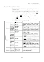
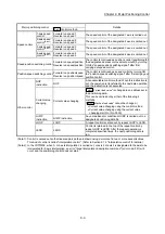
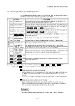
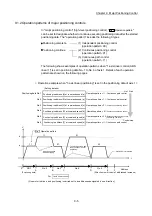
8.2.7 OPR method (5): Scale origin signal detection method
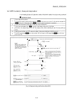
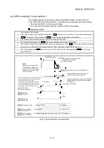
The following shows an operation outline of the OPR method "scale origin signal
detection method".
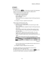
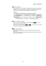
POINT
Set "0: Need to pass servo motor Z-phase after power on" in "Function selection C-
4 (PC17)". If "1: Not need to pass servo motor Z-phase after power on" is set, the
error "Z-phase passing parameter invalid" (error code: 231) will occur at the start of
scale origin signal detection method OPR.
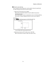
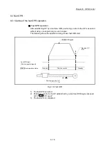
Operation chart
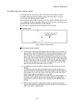
1)
The machine OPR is started.
(The machine begins the acceleration designated in "
Pr.51
OPR acceleration time selection
", in the direction
designated in "
Pr.44
OPR direction
". It then moves at the "
Pr.46
OPR speed
" when the acceleration is
completed.)
2)
The machine begins decelerating when the near-point dog ON is detected.
3)
After deceleration stop, the machine moves in the opposite direction against of OPR at the "
Pr.46
OPR
speed
".
4)
During movement, the machine begins decelerating when the first zero signal is detected.
5)
After deceleration stop, the operation moves in direction of OPR at the "
Pr.47
Creep speed
", and then stops
at the detected nearest zero signal.
6)
The OPR complete flag (
Md.31
Status: b4
) turns from OFF to ON, and the OPR request flag
(
Md.31
Status: b3
) turns from ON to OFF.
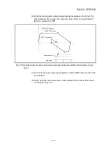
After 3), when the zero signal is in the near-point dog
position, deceleration stop (4)) is started at the zero signal
without waiting for the near-point dog OFF.
Zero signal
ON
1)
2)
OPR direction
POINT
Pr.44
V
6)
3)
5)
4)
OFF
Near-point dog
Hardware limit switch
Pr.46
Pr.47
OPR speed
Creep speed
Fig. 8.11 Scale origin signal detection method machine OPR
Summary of Contents for MELSEC-L Series
Page 2: ......
Page 30: ...MEMO ...
Page 70: ...2 10 Chapter 2 System Configuration MEMO ...
Page 83: ...3 13 Chapter 3 Specifications and Functions MEMO ...
Page 103: ...3 33 Chapter 3 Specifications and Functions MEMO ...
Page 107: ...3 37 Chapter 3 Specifications and Functions MEMO ...
Page 111: ...3 41 Chapter 3 Specifications and Functions MEMO ...
Page 115: ...3 45 Chapter 3 Specifications and Functions MEMO ...
Page 140: ...4 22 Chapter 4 Installation Wiring and Maintenance of the Product MEMO ...
Page 253: ...5 113 Chapter 5 Data Used for Positioning Control MEMO ...
Page 342: ...5 202 Chapter 5 Data Used for Positioning Control MEMO ...
Page 438: ...7 20 Chapter 7 Memory Configuration and Data Process MEMO ...
Page 440: ...MEMO ...
Page 485: ...9 25 Chapter 9 Major Positioning Control MEMO ...
Page 594: ...9 134 Chapter 9 Major Positioning Control MEMO ...
Page 624: ...10 30 Chapter 10 High Level Positioning Control MEMO ...
Page 656: ...11 32 Chapter 11 Manual Control MEMO ...
Page 690: ...12 34 Chapter 12 Expansion Control MEMO ...
Page 798: ...13 108 Chapter 13 Control Sub Functions MEMO ...
Page 866: ...14 68 Chapter 14 Common Functions MEMO ...
Page 884: ...15 18 Chapter 15 Dedicated Instructions MEMO ...
Page 899: ...16 15 Chapter 16 Troubleshooting MEMO ...
Page 1036: ...Appendix 88 Appendices MEMO ...
Page 1039: ......

