


Appendix - 81
Appendices
(2) OPR
The method and some operation of the OPR using the IAI electric actuator
controller differ from those of the OPR using the servo amplifier.
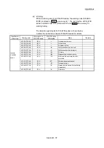
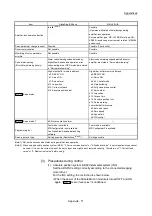
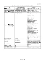
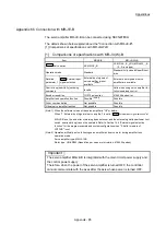
(a) OPR method that can be used
Pr.43
OPR method
Possible/Not possible
Near-point dog method
* 1
Count method 1)
* 1
Count method 2)
* 1
Data set method
* 1
Scale origin signal detection method
* 1
Driver OPR method
: Possible
: Not possible
1: The error "OPR method invalid" (error code: 232) occurs and OPR is not
performed.
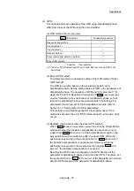
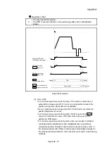
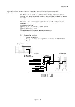
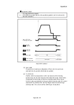
(b) Driver OPR method
The following shows an operation outline of the OPR method "Driver
OPR method".
The OPR is executed based on the positioning pattern set in the IAI
electric actuator controller. Set the setting values of OPR in the
parameters of the IAI electric actuator controller. The operation of OPR
and "b0: Lower limit", "b1: Upper limit" and "b6: Near-point dog signal"
of "
Pr.22
Input signal logic selection
" depend on the specification of the
IAI electric actuator controller, so that refer to the IAI electric actuator
controller manual and match the settings. For parameters that can be
set by the Simple Motion module, refer to Section 5.1.3 "Setting items
for OPR parameters".
This method is not available except for the stepping driver (including
the IAI electric actuator controller). If the method is executed, the error
"OPR method invalid" (error code: 232) occurs.
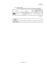
(c) Backlash compensation after the driver OPR method
When "
Pr.11
Backlash compensation amount
" is set in the Simple Motion
module, set the positive direction in "
Pr.44
OPR direction
".
Summary of Contents for MELSEC-L Series
Page 2: ......
Page 30: ...MEMO ...
Page 70: ...2 10 Chapter 2 System Configuration MEMO ...
Page 83: ...3 13 Chapter 3 Specifications and Functions MEMO ...
Page 103: ...3 33 Chapter 3 Specifications and Functions MEMO ...
Page 107: ...3 37 Chapter 3 Specifications and Functions MEMO ...
Page 111: ...3 41 Chapter 3 Specifications and Functions MEMO ...
Page 115: ...3 45 Chapter 3 Specifications and Functions MEMO ...
Page 140: ...4 22 Chapter 4 Installation Wiring and Maintenance of the Product MEMO ...
Page 253: ...5 113 Chapter 5 Data Used for Positioning Control MEMO ...
Page 342: ...5 202 Chapter 5 Data Used for Positioning Control MEMO ...
Page 438: ...7 20 Chapter 7 Memory Configuration and Data Process MEMO ...
Page 440: ...MEMO ...
Page 485: ...9 25 Chapter 9 Major Positioning Control MEMO ...
Page 594: ...9 134 Chapter 9 Major Positioning Control MEMO ...
Page 624: ...10 30 Chapter 10 High Level Positioning Control MEMO ...
Page 656: ...11 32 Chapter 11 Manual Control MEMO ...
Page 690: ...12 34 Chapter 12 Expansion Control MEMO ...
Page 798: ...13 108 Chapter 13 Control Sub Functions MEMO ...
Page 866: ...14 68 Chapter 14 Common Functions MEMO ...
Page 884: ...15 18 Chapter 15 Dedicated Instructions MEMO ...
Page 899: ...16 15 Chapter 16 Troubleshooting MEMO ...
Page 1036: ...Appendix 88 Appendices MEMO ...
Page 1039: ......


