


3 - 11
Chapter 3 Specifications and Functions
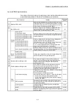
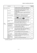
3.2.4 LD77MS common functions
The outline of the functions executed as necessary is described below.
(Refer to "Section 2" for details on each function.)
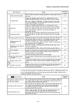
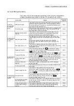
Common functions
Details
Reference
section
Parameter initialization function
This function returns the "parameters" stored in the buffer
memory/internal memory and flash ROM/internal memory
(nonvolatile) of Simple Motion module to the default values.
The following two methods can be used.
1) Method using sequence program
2) Method using GX Works2
14.2
Execution data backup function
This function stores the "setting data", currently being executed,
into the flash ROM/internal memory (nonvolatile).
1) Method using sequence program
2) Method using GX Works2
14.3
External signal selection function
This function selects from the following signals when using the
upper/lower limit signal and the near-point dog signal.
• External input signal of servo amplifier
• External input signal via CPU (buffer memory of LD77MS)
14.4
External I/O signal logic switching function
This function switches I/O signal logic according to externally
connected devices.
This function enables the use of the system that does not use b
(N.C.)-contact signals, such as Upper/lower limit signal, by
setting parameters to positive logic.
14.5
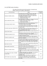
History monitor function
This function monitors errors, warnings, and start history of all
axes.
14.6
Amplifier-less operation function
This function executes the positioning control of Simple Motion
module without connecting to the servo amplifiers.
It is used to debug the program at the start-up of the device or
simulate the positioning operation.
14.7
Virtual servo amplifier function
This function executes the operation as the axis (virtual servo
amplifier axis) that operates only command (instruction) virtually
without servo amplifiers.
14.8
Driver communication function
This function uses the "Master-slave operation function" of servo
amplifier. The Simple Motion module controls the master axis
and the slave axis is controlled by data communication between
servo amplifiers (driver communication) without Simple Motion
module.
14.9
Mark detection function
This function is used to latch any data at the input timing of the
mark detection signal (DI1 to DI4).
14.10
Optional data monitor function
This function is used to store the data selected by user up to 4
data per axis to buffer memory and monitor them.
14.11
Module error collection function
This function collects errors occurred in the Simple Motion
module in the PLC CPU.
Holding the error contents in the PLC CPU, this function enables
to check the error history even after the PLC CPU in powered off
or reset.
14.12
Connect/disconnect function of SSCNET
communication
Temporarily connect/disconnect of SSCNET communication is
executed during system's power supply ON.
This function is used to exchange the servo amplifiers or
SSCNET cables.
14.13
LD77MH initial value setting function
This function is used to set the factory-set initial value of
LD77MH for the setting data set in the LD77MS buffer
memory/internal memory and flash ROM/internal memory
(nonvolatile).
14.14
Summary of Contents for MELSEC-L Series
Page 2: ......
Page 30: ...MEMO ...
Page 70: ...2 10 Chapter 2 System Configuration MEMO ...
Page 83: ...3 13 Chapter 3 Specifications and Functions MEMO ...
Page 103: ...3 33 Chapter 3 Specifications and Functions MEMO ...
Page 107: ...3 37 Chapter 3 Specifications and Functions MEMO ...
Page 111: ...3 41 Chapter 3 Specifications and Functions MEMO ...
Page 115: ...3 45 Chapter 3 Specifications and Functions MEMO ...
Page 140: ...4 22 Chapter 4 Installation Wiring and Maintenance of the Product MEMO ...
Page 253: ...5 113 Chapter 5 Data Used for Positioning Control MEMO ...
Page 342: ...5 202 Chapter 5 Data Used for Positioning Control MEMO ...
Page 438: ...7 20 Chapter 7 Memory Configuration and Data Process MEMO ...
Page 440: ...MEMO ...
Page 485: ...9 25 Chapter 9 Major Positioning Control MEMO ...
Page 594: ...9 134 Chapter 9 Major Positioning Control MEMO ...
Page 624: ...10 30 Chapter 10 High Level Positioning Control MEMO ...
Page 656: ...11 32 Chapter 11 Manual Control MEMO ...
Page 690: ...12 34 Chapter 12 Expansion Control MEMO ...
Page 798: ...13 108 Chapter 13 Control Sub Functions MEMO ...
Page 866: ...14 68 Chapter 14 Common Functions MEMO ...
Page 884: ...15 18 Chapter 15 Dedicated Instructions MEMO ...
Page 899: ...16 15 Chapter 16 Troubleshooting MEMO ...
Page 1036: ...Appendix 88 Appendices MEMO ...
Page 1039: ......


