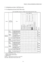


7 - 8
Chapter 7 Memory Configuration and Data Process
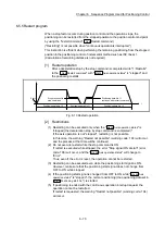
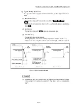
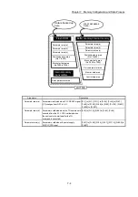
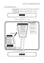
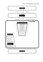
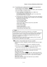
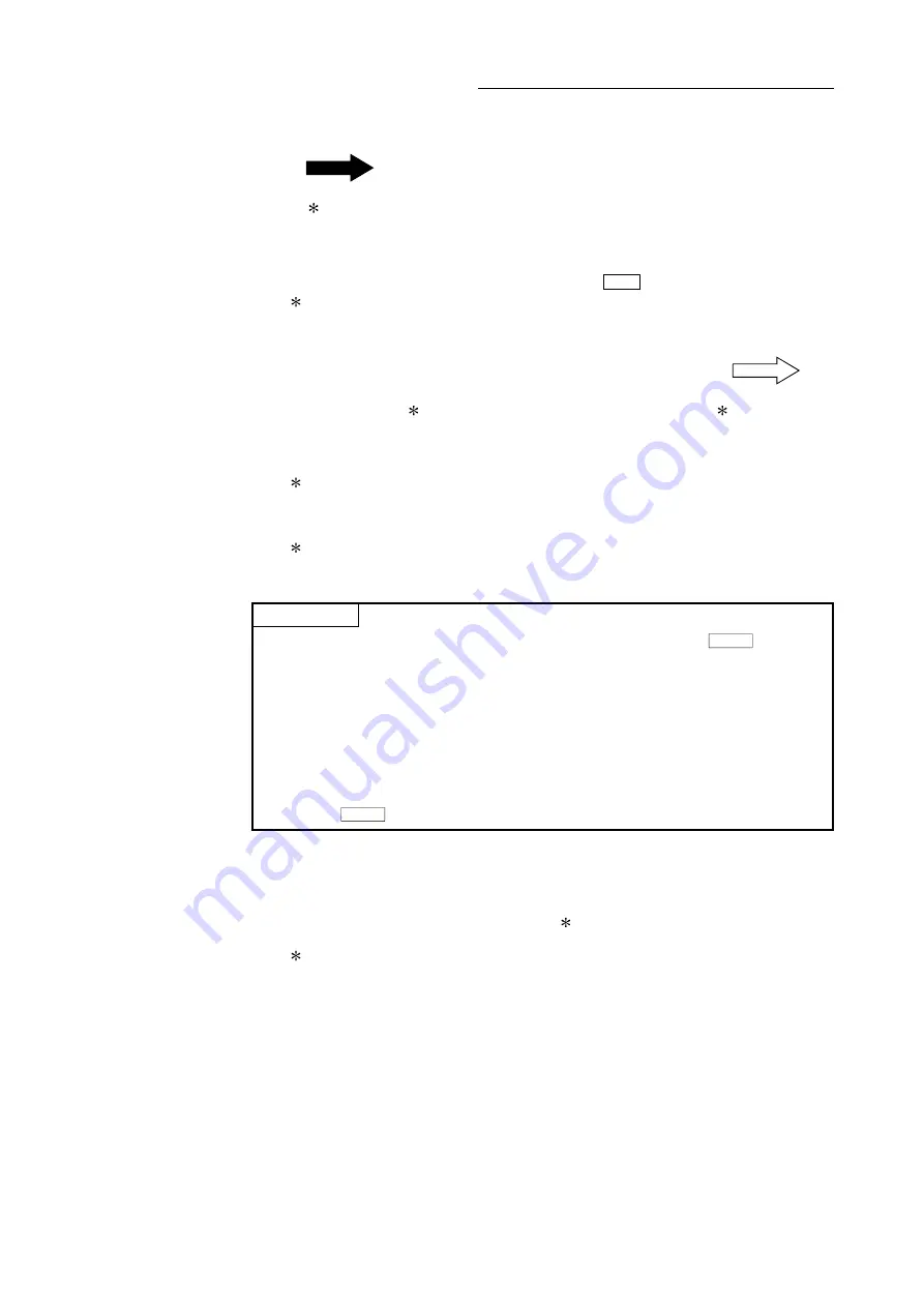
(1) Transmitting data when power is turned ON or PLC CPU is reset
(
)
When the power is turned ON or the PLC CPU is reset, the "parameters area
(c)
1
", "positioning data", "block start data" and "servo parameter" stored
(backed up) in the flash ROM/internal memory (nonvolatile) are transmitted to the
buffer memory and internal memory.
The value stored in the flash ROM is valid for "
Pr.96
Operation cycle setting
".
1: For details of area, refer to Section 7.1.1 "Configuration and roles of
LD77MS memory".
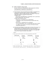
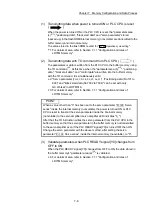
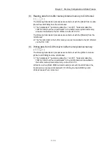
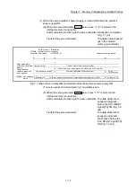
(2) Transmitting data with TO command from PLC CPU (
)
The parameters or data is written from the PLC CPU to the buffer memory using
the TO command
2
. At this time, when the "parameter area (b)
3
", "positioning
data", "block start data", and "control data" are written into the buffer memory
with the TO command, it is simultaneously valid.
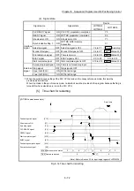
2: "Servo parameter (
PA19, PD, PE, PS, PF, Po, PL
)", "Positioning data (No.101 to
600)" and "Block start data (No.7002 to 7004)" can be set with only
GX Works2 in LD77MS16.
3: For details of area, refer to Section 7.1.1 "Configuration and roles of
LD77MS memory".
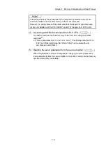
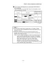
POINT
When a value other than "0" has been set to the servo parameter "
Pr.100
Servo
series" inside the internal memory (nonvolatile), the power is turned ON or PLC
CPU is reset to transmit the servo parameter inside the internal memory
(nonvolatile) to the servo amplifier (servo amplifier LED indicates "b_").
After that, the TO instruction writes the servo parameter from the PLC CPU to the
buffer memory so that the servo parameter in the buffer memory is not transmitted
to the servo amplifier even if the PLC READY signal [Y0] is turned OFF then ON.
Change the servo parameter with the above method, after setting the servo
parameter "
Pr.100
Servo series" inside the internal memory (nonvolatile), to "0".
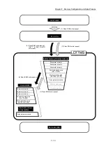
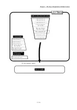
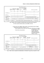
(3) Validate parameters when PLC READY signal [Y0] changes from
OFF to ON
When the PLC READY signal [Y0] changes from OFF to ON, the data stored in
the buffer memory's "parameter area (a)
4
" is validated.
4: For details of area, refer to Section 7.1.1 "Configuration and roles of
LD77MS memory".
Summary of Contents for MELSEC-L Series
Page 2: ......
Page 30: ...MEMO ...
Page 70: ...2 10 Chapter 2 System Configuration MEMO ...
Page 83: ...3 13 Chapter 3 Specifications and Functions MEMO ...
Page 103: ...3 33 Chapter 3 Specifications and Functions MEMO ...
Page 107: ...3 37 Chapter 3 Specifications and Functions MEMO ...
Page 111: ...3 41 Chapter 3 Specifications and Functions MEMO ...
Page 115: ...3 45 Chapter 3 Specifications and Functions MEMO ...
Page 140: ...4 22 Chapter 4 Installation Wiring and Maintenance of the Product MEMO ...
Page 253: ...5 113 Chapter 5 Data Used for Positioning Control MEMO ...
Page 342: ...5 202 Chapter 5 Data Used for Positioning Control MEMO ...
Page 438: ...7 20 Chapter 7 Memory Configuration and Data Process MEMO ...
Page 440: ...MEMO ...
Page 485: ...9 25 Chapter 9 Major Positioning Control MEMO ...
Page 594: ...9 134 Chapter 9 Major Positioning Control MEMO ...
Page 624: ...10 30 Chapter 10 High Level Positioning Control MEMO ...
Page 656: ...11 32 Chapter 11 Manual Control MEMO ...
Page 690: ...12 34 Chapter 12 Expansion Control MEMO ...
Page 798: ...13 108 Chapter 13 Control Sub Functions MEMO ...
Page 866: ...14 68 Chapter 14 Common Functions MEMO ...
Page 884: ...15 18 Chapter 15 Dedicated Instructions MEMO ...
Page 899: ...16 15 Chapter 16 Troubleshooting MEMO ...
Page 1036: ...Appendix 88 Appendices MEMO ...
Page 1039: ......


