

4 - 4
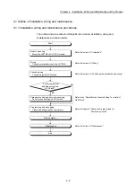
Chapter 4 Installation, Wiring and Maintenance of the Product
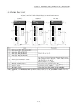
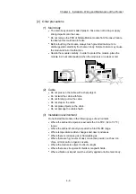
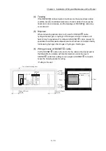
(2) The LED display indicates the following operation statuses of the Simple Motion
module and axes.
LD77MS2
LD77MS16
LD77MS4
LD77MS4
RUN
ERR.
AX
1
2
3
4
LD77MS16
RUN
ERR.
AX 1
9 10111213141516
2 3 4 5 6 7 8
LD77MS2
RUN
ERR.
AX
1
2
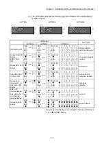
LED Display
Description
LD77MS2
LD77MS4
LD77MS16
RUN LED is OFF.
RUN
ERR.
AX
1
2
RUN
ERR.
AX
1
2
3
4
RUN
ERR.
AX 1 2 3 4 5 6 7 8
9 10 11 12 13 14 15 16
Hardware failure,
watch dog timer error
Steady RUN LED
display.
ERR. LED is
OFF.
RUN
ERR.
AX
1
2
RUN
ERR.
AX
1
2
3
4
RUN
ERR.
AX 1 2 3 4 5 6 7 8
9 10 11 12 13 14 15 16
The module operates
normally.
Steady ERR. LED
display.
RUN
ERR.
AX
1
2
RUN
ERR.
AX
1
2
3
4
RUN
ERR.
AX 1 2 3 4 5 6 7 8
9 10 11 12 13 14 15 16
System error
Axis information 1
to 16 are OFF.
RUN
ERR.
AX
1
2
RUN
ERR.
AX
1
2
3
4
RUN
ERR.
AX 1 2 3 4 5 6 7 8
9 10 11 12 13 14 15 16
During axis stop,
during axis standby.
Steady Axis
information 1 (or
other axis) LED
display.
RUN
ERR.
AX
1
2
RUN
ERR.
AX
1
2
3
4
RUN
ERR.
AX 1 2 3 4 5 6 7 8
9 10 11 12 13 14 15 16
During axis
operation.
ERR. LED
remains flashing.
Axis information 1
(or other axis)
remains flashing.
RUN
ERR.
AX 1
2
RUN
ERR.
AX
1
2
3
4
RUN
ERR.
AX 1 2 3 4 5 6 7 8
9 10 11 12 13 14 15 16
Axis error
Steady all LEDs
display.
RUN
ERR.
AX
1
2
RUN
ERR.
AX
1
2
3
4
RUN
ERR.
AX 1 2 3 4 5 6 7 8
9 10 11 12 13 14 15 16
Hardware failure
The symbols in the Display column indicate the following LED statuses:
: OFF, : ON,
: Flashing
Summary of Contents for MELSEC-L Series
Page 2: ......
Page 30: ...MEMO ...
Page 70: ...2 10 Chapter 2 System Configuration MEMO ...
Page 83: ...3 13 Chapter 3 Specifications and Functions MEMO ...
Page 103: ...3 33 Chapter 3 Specifications and Functions MEMO ...
Page 107: ...3 37 Chapter 3 Specifications and Functions MEMO ...
Page 111: ...3 41 Chapter 3 Specifications and Functions MEMO ...
Page 115: ...3 45 Chapter 3 Specifications and Functions MEMO ...
Page 140: ...4 22 Chapter 4 Installation Wiring and Maintenance of the Product MEMO ...
Page 253: ...5 113 Chapter 5 Data Used for Positioning Control MEMO ...
Page 342: ...5 202 Chapter 5 Data Used for Positioning Control MEMO ...
Page 438: ...7 20 Chapter 7 Memory Configuration and Data Process MEMO ...
Page 440: ...MEMO ...
Page 485: ...9 25 Chapter 9 Major Positioning Control MEMO ...
Page 594: ...9 134 Chapter 9 Major Positioning Control MEMO ...
Page 624: ...10 30 Chapter 10 High Level Positioning Control MEMO ...
Page 656: ...11 32 Chapter 11 Manual Control MEMO ...
Page 690: ...12 34 Chapter 12 Expansion Control MEMO ...
Page 798: ...13 108 Chapter 13 Control Sub Functions MEMO ...
Page 866: ...14 68 Chapter 14 Common Functions MEMO ...
Page 884: ...15 18 Chapter 15 Dedicated Instructions MEMO ...
Page 899: ...16 15 Chapter 16 Troubleshooting MEMO ...
Page 1036: ...Appendix 88 Appendices MEMO ...
Page 1039: ......


