


5 - 158
Chapter 5 Data Used for Positioning Control
5.7 List of control data
The setting items of the control data are explained in this section.
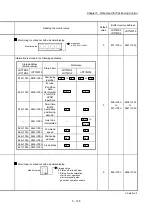
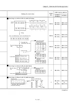
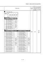
• Guide to buffer memory address
In the buffer memory address, "n" in "4303+100n", etc. indicates a value
corresponding to axis No. such as the following table.
Axis No.
n
Axis No.
n
Axis No.
n
Axis No.
n
1 0 5 4 9 8 13 12
2 1 6 5 10 9 14 13
3 2 7 6 11 10 15 14
4 3 8 7 12 11 16 15
(Note-1): Calculate as follows for the buffer memory address corresponding to each axis.
(Example) For axis No. 16
4303+100n (
Cd.6
Restart command)=4303+100 15=5803
(Note-2): The range from axis No.1 to 2 (n=0 to 1) is valid in the LD77MS2.
(Note-3): The range from axis No.1 to 4 (n=0 to 3) is valid in the LD77MS4.
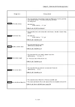
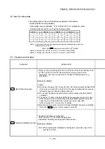
5.7.1 System control data
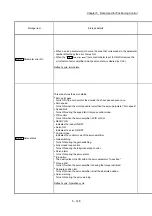
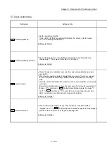
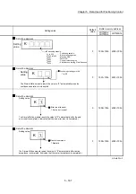
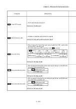
Setting item
Setting details
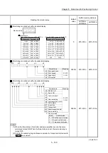
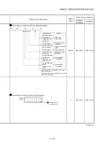
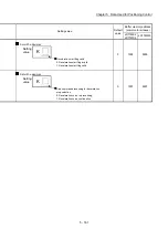
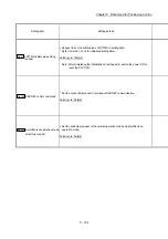
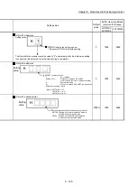
Cd.1
Flash ROM write request
Writes not only "positioning data (No.1 to 600)" and "block start data (No.7000
to 7004)" stored in the buffer memory/internal memory area, but also
"parameters" and "servo parameters" to the flash ROM/internal memory
(nonvolatile).
Fetch cycle: 103[ms]
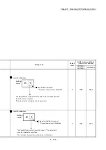
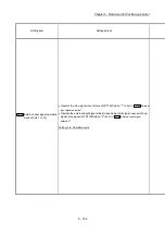
POINT
(1) Do not turn the power OFF or reset the PLC CPU while writing to the flash ROM.
If the power is turned OFF or the PLC CPU is reset to forcibly end the process,
the data backed up in the flash ROM will be lost.
(2) Do not write the data to the buffer memory before writing to the flash ROM is
completed.
(3) The number of writes to the flash ROM with the sequence program is 25 max.
while the power is turned ON. Writing to the flash ROM beyond 25 times will
cause the error "Flash ROM write number error" (error code: 805).
Refer to Section 16.5 "List of errors" for details.
(4) Monitoring is the number of writes to the flash ROM after the power is switched
ON by the "
Md.19
Number
of write accesses to flash ROM
".
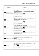
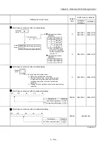
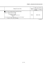
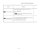
Cd.2
Parameter initialization request
Requests initialization of setting data.
Refer to Section 14.2 for initialized setting data.
Initialization: Resetting of setting data to default values
Fetch cycle: 103[ms]
Note: After completing the initialization of setting data, switch the power ON or
reset the PLC CPU.
Summary of Contents for MELSEC-L Series
Page 2: ......
Page 30: ...MEMO ...
Page 70: ...2 10 Chapter 2 System Configuration MEMO ...
Page 83: ...3 13 Chapter 3 Specifications and Functions MEMO ...
Page 103: ...3 33 Chapter 3 Specifications and Functions MEMO ...
Page 107: ...3 37 Chapter 3 Specifications and Functions MEMO ...
Page 111: ...3 41 Chapter 3 Specifications and Functions MEMO ...
Page 115: ...3 45 Chapter 3 Specifications and Functions MEMO ...
Page 140: ...4 22 Chapter 4 Installation Wiring and Maintenance of the Product MEMO ...
Page 253: ...5 113 Chapter 5 Data Used for Positioning Control MEMO ...
Page 342: ...5 202 Chapter 5 Data Used for Positioning Control MEMO ...
Page 438: ...7 20 Chapter 7 Memory Configuration and Data Process MEMO ...
Page 440: ...MEMO ...
Page 485: ...9 25 Chapter 9 Major Positioning Control MEMO ...
Page 594: ...9 134 Chapter 9 Major Positioning Control MEMO ...
Page 624: ...10 30 Chapter 10 High Level Positioning Control MEMO ...
Page 656: ...11 32 Chapter 11 Manual Control MEMO ...
Page 690: ...12 34 Chapter 12 Expansion Control MEMO ...
Page 798: ...13 108 Chapter 13 Control Sub Functions MEMO ...
Page 866: ...14 68 Chapter 14 Common Functions MEMO ...
Page 884: ...15 18 Chapter 15 Dedicated Instructions MEMO ...
Page 899: ...16 15 Chapter 16 Troubleshooting MEMO ...
Page 1036: ...Appendix 88 Appendices MEMO ...
Page 1039: ......


