
14 - 15
Chapter 14 Common Functions
14.5 External I/O signal logic switching function
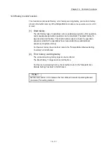
This function switches the signal logic according to the following signals.
• External equipment connected to Simple Motion module
• External input signal of servo amplifier (upper/lower limit switch, near-point dog)
For the system in which b-contact, upper limit switch, and lower limit switch are not
used, the parameter logic setting can be controlled without wiring if it is changed to a
"positive logic".
When the upper limit switch, and lower limit switch are used, ensure to use them with
negative logic (b-contact).
The details shown below explain about the "External I/O signal logic switching
function".
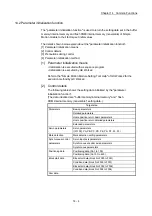
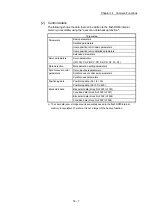
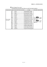
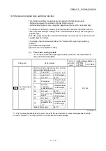
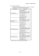
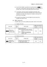
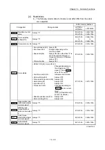
[1] Parameter setting details
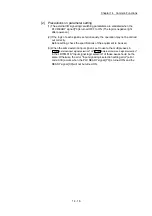
[2] Precautions on parameter setting
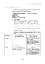
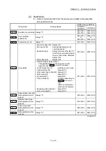
[1] Parameter setting details
To use the "External I/O signal logic switching function", set the parameters
shown in the following table.
Setting item
Setting details
Factory-
set initial
value
Buffer memory address
LD77MS2
LD77MS4
LD77MS16
Pr.22
Input signal logic
selection
• Selection of logic of signals input from external
device to Simple Motion module
0 31+150n
b0
Lower limit
0: Negative logic,
1: Positive logic
b1
Upper limit
b2
Not used
Set "0".
b3 Stop
signal
0: Negative logic,
1: Positive logic
b4
External
command/
switching signal
0: Negative logic,
1: Positive logic
b5
Not used
Set "0".
b6
Near-point dog
signal
0: Negative logic,
1: Positive logic
b7
Not used
Set "0".
b8
Manual pulse
generator input
1
0: Negative logic,
1: Positive logic
b9 to b15 Not used
Set "0".
n: Axis No.-1
1: Only the value specified against the axis 1 is valid for the logic selection of manual pulse generator input (b8).
: Refer to Section 5.2 "List of parameters" for the information on detail settings.
Summary of Contents for MELSEC-L Series
Page 2: ......
Page 30: ...MEMO ...
Page 70: ...2 10 Chapter 2 System Configuration MEMO ...
Page 83: ...3 13 Chapter 3 Specifications and Functions MEMO ...
Page 103: ...3 33 Chapter 3 Specifications and Functions MEMO ...
Page 107: ...3 37 Chapter 3 Specifications and Functions MEMO ...
Page 111: ...3 41 Chapter 3 Specifications and Functions MEMO ...
Page 115: ...3 45 Chapter 3 Specifications and Functions MEMO ...
Page 140: ...4 22 Chapter 4 Installation Wiring and Maintenance of the Product MEMO ...
Page 253: ...5 113 Chapter 5 Data Used for Positioning Control MEMO ...
Page 342: ...5 202 Chapter 5 Data Used for Positioning Control MEMO ...
Page 438: ...7 20 Chapter 7 Memory Configuration and Data Process MEMO ...
Page 440: ...MEMO ...
Page 485: ...9 25 Chapter 9 Major Positioning Control MEMO ...
Page 594: ...9 134 Chapter 9 Major Positioning Control MEMO ...
Page 624: ...10 30 Chapter 10 High Level Positioning Control MEMO ...
Page 656: ...11 32 Chapter 11 Manual Control MEMO ...
Page 690: ...12 34 Chapter 12 Expansion Control MEMO ...
Page 798: ...13 108 Chapter 13 Control Sub Functions MEMO ...
Page 866: ...14 68 Chapter 14 Common Functions MEMO ...
Page 884: ...15 18 Chapter 15 Dedicated Instructions MEMO ...
Page 899: ...16 15 Chapter 16 Troubleshooting MEMO ...
Page 1036: ...Appendix 88 Appendices MEMO ...
Page 1039: ......


