


5 - 150
Chapter 5 Data Used for Positioning Control
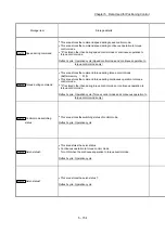
Storage item
Storage details
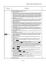
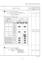
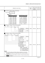
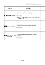
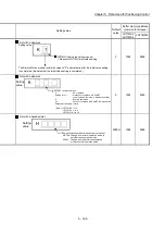
Md.109
Regenerative load ratio/
Optional data monitor output
1
The rate of regenerative power to the allowable regenerative power is indicated
as a percentage.
When the regenerative option is used, the rate to the allowable regenerative
power of the option is indicated.
(Buffer memory) %
This area stores the content set in "
Pr.91
Optional data monitor: Data type setting 1
"
at optional data monitor data type setting.
Refresh cycle: Operation cycle
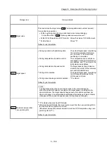
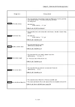
Md.110
Effective load torque/
Optional data monitor output
2
The continuous effective load torque is indicated.
The average value of the load rates for the past 15 seconds to the rated torque is
stored as a percentage, rated torque being 100%.
(Buffer memory) %
This area stores the content set in "
Pr.92
Optional data monitor: Data type setting 2
"
at optional data monitor data type setting.
Refresh cycle: Operation cycle
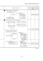
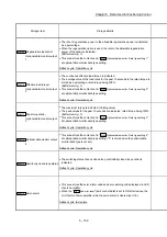
Md.111
Peak torque ratio/
Optional data monitor output
3
The maximum torque is indicated. (Holding value)
The peak values for the past 15 seconds are indicated, rated torque being 100%.
(Buffer memory) %
This area stores the content set in "
Pr.93
Optional data monitor: Data type setting 3
"
at optional data monitor data type setting.
Refresh cycle: Operation cycle
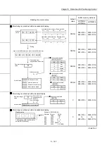
Md.112
Optional data monitor output
4
This area stores the content set in "
Pr.94
Optional data monitor: Data type setting 4
"
at optional data monitor data type setting. ("0" is stored when the optional data
monitor data type is not set.)
Refresh cycle: Operation cycle
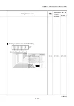
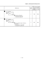
Md.113
Semi/Fully closed loop status
The switching status of semi closed loop control/fully closed loop control is
indicated.
Refresh cycle: Operation cycle
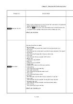
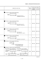
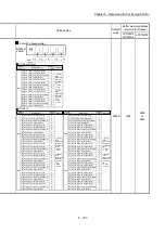
Md.114
Servo alarm
This area stores the servo alarm code and servo warning code displayed in LED
of servo amplifier.
When the "
Cd.5
Axis error reset
" (axis control data) is set to ON after remove the
error factor of servo amplifier side, the servo alarm is cleared (set to 0).
Refresh cycle: Immediate
Summary of Contents for MELSEC-L Series
Page 2: ......
Page 30: ...MEMO ...
Page 70: ...2 10 Chapter 2 System Configuration MEMO ...
Page 83: ...3 13 Chapter 3 Specifications and Functions MEMO ...
Page 103: ...3 33 Chapter 3 Specifications and Functions MEMO ...
Page 107: ...3 37 Chapter 3 Specifications and Functions MEMO ...
Page 111: ...3 41 Chapter 3 Specifications and Functions MEMO ...
Page 115: ...3 45 Chapter 3 Specifications and Functions MEMO ...
Page 140: ...4 22 Chapter 4 Installation Wiring and Maintenance of the Product MEMO ...
Page 253: ...5 113 Chapter 5 Data Used for Positioning Control MEMO ...
Page 342: ...5 202 Chapter 5 Data Used for Positioning Control MEMO ...
Page 438: ...7 20 Chapter 7 Memory Configuration and Data Process MEMO ...
Page 440: ...MEMO ...
Page 485: ...9 25 Chapter 9 Major Positioning Control MEMO ...
Page 594: ...9 134 Chapter 9 Major Positioning Control MEMO ...
Page 624: ...10 30 Chapter 10 High Level Positioning Control MEMO ...
Page 656: ...11 32 Chapter 11 Manual Control MEMO ...
Page 690: ...12 34 Chapter 12 Expansion Control MEMO ...
Page 798: ...13 108 Chapter 13 Control Sub Functions MEMO ...
Page 866: ...14 68 Chapter 14 Common Functions MEMO ...
Page 884: ...15 18 Chapter 15 Dedicated Instructions MEMO ...
Page 899: ...16 15 Chapter 16 Troubleshooting MEMO ...
Page 1036: ...Appendix 88 Appendices MEMO ...
Page 1039: ......


