13 - 62
Chapter 13 Control Sub Functions
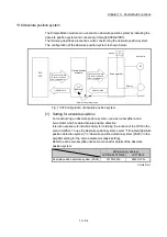
[3] Method of setting target position change function from PLC CPU
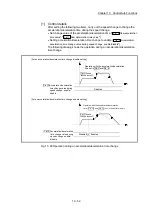
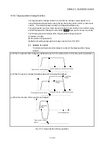
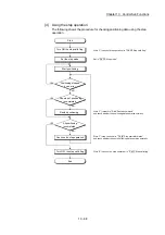
The following table and chart show the example of a data setting and sequence
program used to change the target position of the axis 1 by the command from
the PLC CPU, respectively. (example in which the target position value and
command speed are changed to a new target position of "300.0 m" and a new
command speed of "10000.00 mm/min".)
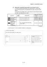
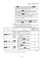
(1) The following data is set.
(Referring to the target position change time chart shown in item (2) below,
carry out the setting with the sequence program shown in item (3).)
Setting item
Setting
value
Setting details
Buffer memory address
LD77MS2
LD77MS4
LD77MS16
Cd.27
Target position
change value
(New address)
3000 Set the new address.
1534+100n
1535+100n
4334+100n
4335+100n
Cd.28
Target position
change value
(New speed)
1000000 Set the new speed.
1536+100n
1537+100n
4336+100n
4337+100n
Cd.29
Target position
change request
flag
1
Set "1: Requests a change in the target
position".
1538+100n 4338+100n
n: Axis No.-1
: Refer to Section 5.7 "List of control data" for details on the setting details.
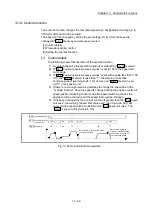
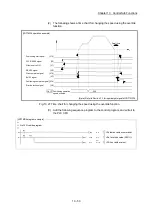
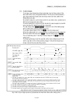
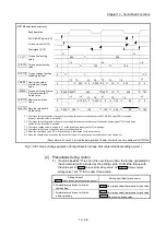
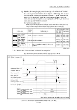
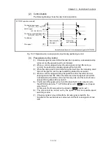
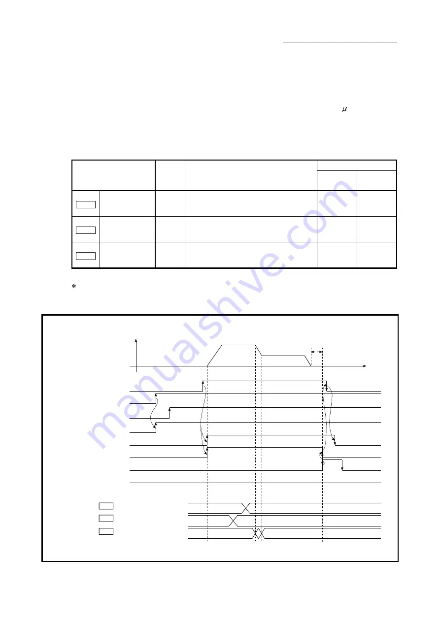
(2) The following shows the time chart for target position change.
[LD77MS4 operation example]
PLC READY signal [Y0]
READY signal [X0]
Start complete signal [X10]
BUSY signal [XC]
Error detection signal [X8]
V
t
Positioning start signal [Y10]
1000000
3000
Positioning complete signal [X14]
Dwell time
Cd.27
Cd.28
1
0
0
Cd.29
All axis servo ON [Y1]
Target position change value
(New address)
Target position change value
(New speed)
Target position change request
flag
(Note): Refer to Section 3.3 for input/output signal of LD77MS16.
Fig. 13.32 Time chart for target position change from PLC CPU
Summary of Contents for MELSEC-L Series
Page 2: ......
Page 30: ...MEMO ...
Page 70: ...2 10 Chapter 2 System Configuration MEMO ...
Page 83: ...3 13 Chapter 3 Specifications and Functions MEMO ...
Page 103: ...3 33 Chapter 3 Specifications and Functions MEMO ...
Page 107: ...3 37 Chapter 3 Specifications and Functions MEMO ...
Page 111: ...3 41 Chapter 3 Specifications and Functions MEMO ...
Page 115: ...3 45 Chapter 3 Specifications and Functions MEMO ...
Page 140: ...4 22 Chapter 4 Installation Wiring and Maintenance of the Product MEMO ...
Page 253: ...5 113 Chapter 5 Data Used for Positioning Control MEMO ...
Page 342: ...5 202 Chapter 5 Data Used for Positioning Control MEMO ...
Page 438: ...7 20 Chapter 7 Memory Configuration and Data Process MEMO ...
Page 440: ...MEMO ...
Page 485: ...9 25 Chapter 9 Major Positioning Control MEMO ...
Page 594: ...9 134 Chapter 9 Major Positioning Control MEMO ...
Page 624: ...10 30 Chapter 10 High Level Positioning Control MEMO ...
Page 656: ...11 32 Chapter 11 Manual Control MEMO ...
Page 690: ...12 34 Chapter 12 Expansion Control MEMO ...
Page 798: ...13 108 Chapter 13 Control Sub Functions MEMO ...
Page 866: ...14 68 Chapter 14 Common Functions MEMO ...
Page 884: ...15 18 Chapter 15 Dedicated Instructions MEMO ...
Page 899: ...16 15 Chapter 16 Troubleshooting MEMO ...
Page 1036: ...Appendix 88 Appendices MEMO ...
Page 1039: ......


