
5 - 53
Chapter 5 Data Used for Positioning Control
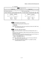
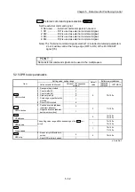
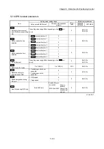
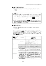
Pr.43
OPR method
Set the "OPR method" for carrying out machine OPR.
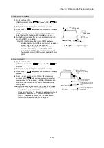
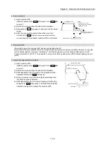
0: Near-point dog method ......... After decelerating at the near-point dog ON, stop
at the zero signal and complete the machine OPR.
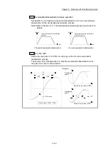
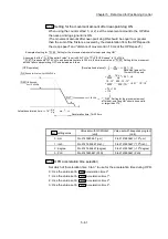
4: Count method 1) ................... After decelerating at the near-point dog ON, move
the designated distance, and complete the
machine OPR with the zero signal.
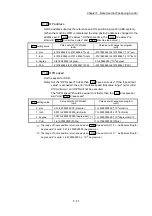
5: Count method 2) ................... After decelerating at the near-point dog ON, move
the designated distance, and complete the
machine OPR.
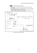
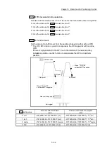
6: Data set method .................... The position where the machine OPR has been
made will be the OP.
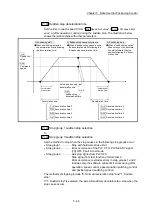
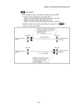
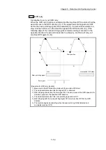
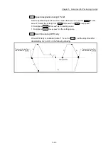
7: Scale origin signal
detection method ................... After deceleration stop at the near-point dog ON,
move to the opposite direction against the OPR
direction, and move to the OPR direction after
deceleration stop once at the detection of the first
zero signal. Then, it stops at the detected nearest
zero signal, and completes the machine OPR.
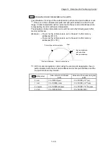
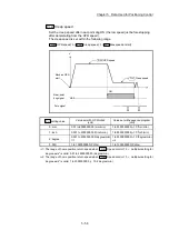
8: Driver OPR method............... Carry out the OPR operation on the driver side.
The OPR operation and parameters depend on
the specifications of the driver. Refer to Appendix
6.3 "AlphaStep/5-phase stepping motor driver
manufactured by ORIENTAL MOTOR Co., Ltd." or
Appendix 6.4 "IAI electric actuator controller
manufactured by IAI Corporation" for details on
the driver OPR method.
When OPR method that cannot be executed is set, the error "OPR method
invalid
" (error code: 232) occurs and the OPR is not executed.
Note) Refer to Section 8.2 "Machine OPR" for details on the OPR methods.
Summary of Contents for MELSEC-L Series
Page 2: ......
Page 30: ...MEMO ...
Page 70: ...2 10 Chapter 2 System Configuration MEMO ...
Page 83: ...3 13 Chapter 3 Specifications and Functions MEMO ...
Page 103: ...3 33 Chapter 3 Specifications and Functions MEMO ...
Page 107: ...3 37 Chapter 3 Specifications and Functions MEMO ...
Page 111: ...3 41 Chapter 3 Specifications and Functions MEMO ...
Page 115: ...3 45 Chapter 3 Specifications and Functions MEMO ...
Page 140: ...4 22 Chapter 4 Installation Wiring and Maintenance of the Product MEMO ...
Page 253: ...5 113 Chapter 5 Data Used for Positioning Control MEMO ...
Page 342: ...5 202 Chapter 5 Data Used for Positioning Control MEMO ...
Page 438: ...7 20 Chapter 7 Memory Configuration and Data Process MEMO ...
Page 440: ...MEMO ...
Page 485: ...9 25 Chapter 9 Major Positioning Control MEMO ...
Page 594: ...9 134 Chapter 9 Major Positioning Control MEMO ...
Page 624: ...10 30 Chapter 10 High Level Positioning Control MEMO ...
Page 656: ...11 32 Chapter 11 Manual Control MEMO ...
Page 690: ...12 34 Chapter 12 Expansion Control MEMO ...
Page 798: ...13 108 Chapter 13 Control Sub Functions MEMO ...
Page 866: ...14 68 Chapter 14 Common Functions MEMO ...
Page 884: ...15 18 Chapter 15 Dedicated Instructions MEMO ...
Page 899: ...16 15 Chapter 16 Troubleshooting MEMO ...
Page 1036: ...Appendix 88 Appendices MEMO ...
Page 1039: ......


