


3 - 35
Chapter 3 Specifications and Functions
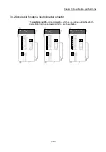
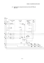
MCCB2
2
A
L1
L2
L3
U
W
V
L11
L21
CN1A
CN1B
DICOM
ALM
EM2/1
DOCOM
MR-J4-B
M
24VDC
U
V
W
Ground
Electro-
magnetic
brake
0
B
L1
L2
L3
U
W
V
L11
L21
CN1A
CN1B
DICOM
ALM
EM2/1
DOCOM
MR-J4-B
M
24VDC
U
V
W
Ground
Electro-
magnetic
brake
1
C
L1
L2
L3
U
W
V
L11
L21
CN1A
CN1B
DICOM
ALM
EM2/1
DOCOM
MR-J4-B
24VDC
U
V
W
Ground
Electro-
magnetic
brake
MC3
SSCNET (/H)
3
4
2
3
4
2
3
4
2
6
MCCB4
MC2
6
MCCB3
6
MC1
B
RA2
U
B
RA3
U
M
B
RA4
U
RA2
RA3
RA4
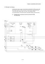
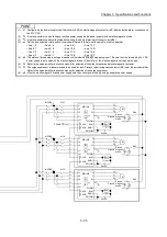
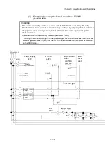
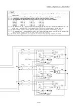
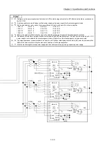
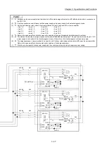
POINT
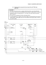
(1) 1: Configure up the power supply circuit which switch off the electromagnetic contactor (MC) after detection alarm occurrence on
the PLC CPU.
(2) 2: It is also possible to use a full wave rectified power supply as the power supply for the electromagnetic brake.
(3) 3: It is also possible to perform the forced stop using forced stop terminal of the servo amplifier.
(4) 4: Set the axis selection rotary switch of servo amplifier as follows to set the axis No. of servo amplifier.
• Axis 1: 0
• Axis 5: 4
• Axis 9: 8
• Axis 13: C
• Axis 2: 1
• Axis 6: 5
• Axis 10: 9
• Axis 14: D
• Axis 3: 2
• Axis 7: 6
• Axis 11: A
• Axis 15: E
• Axis 4: 3
• Axis 8: 7
• Axis 12: B
• Axis 16: F
(5) 5: The status of forced stop input signal can be confirmed with " Md.50 Forced stop input". Be sure that the forced stop 24 V DC
power supply is not used with the electromagnetic brake of the motor or the electromagnetic valve power supply.
(6) 6: Refer to the servo amplifier instruction manual for selection of the circuit breaker and electromagnetic contactor.
(7) 7: The surge suppressor is recommended to be used for an AC relay or electromagnetic contactor (MC) near the servo amplifier.
Refer to the servo amplifier instruction manual for selection of the surge suppressor.
(8) 8: Wire the electromagnetic brake power supply and the control power supply using a separate power supply.
Summary of Contents for MELSEC-L Series
Page 2: ......
Page 30: ...MEMO ...
Page 70: ...2 10 Chapter 2 System Configuration MEMO ...
Page 83: ...3 13 Chapter 3 Specifications and Functions MEMO ...
Page 103: ...3 33 Chapter 3 Specifications and Functions MEMO ...
Page 107: ...3 37 Chapter 3 Specifications and Functions MEMO ...
Page 111: ...3 41 Chapter 3 Specifications and Functions MEMO ...
Page 115: ...3 45 Chapter 3 Specifications and Functions MEMO ...
Page 140: ...4 22 Chapter 4 Installation Wiring and Maintenance of the Product MEMO ...
Page 253: ...5 113 Chapter 5 Data Used for Positioning Control MEMO ...
Page 342: ...5 202 Chapter 5 Data Used for Positioning Control MEMO ...
Page 438: ...7 20 Chapter 7 Memory Configuration and Data Process MEMO ...
Page 440: ...MEMO ...
Page 485: ...9 25 Chapter 9 Major Positioning Control MEMO ...
Page 594: ...9 134 Chapter 9 Major Positioning Control MEMO ...
Page 624: ...10 30 Chapter 10 High Level Positioning Control MEMO ...
Page 656: ...11 32 Chapter 11 Manual Control MEMO ...
Page 690: ...12 34 Chapter 12 Expansion Control MEMO ...
Page 798: ...13 108 Chapter 13 Control Sub Functions MEMO ...
Page 866: ...14 68 Chapter 14 Common Functions MEMO ...
Page 884: ...15 18 Chapter 15 Dedicated Instructions MEMO ...
Page 899: ...16 15 Chapter 16 Troubleshooting MEMO ...
Page 1036: ...Appendix 88 Appendices MEMO ...
Page 1039: ......


