


9 - 10
Chapter 9 Major Positioning Control
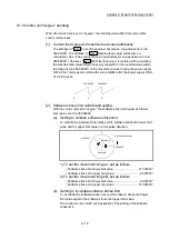
(b) During operation by step operation. (Refer to Section 13.7.1 "Step
function".)
(c) When there is an error in the positioning data to carry out the next
operation.
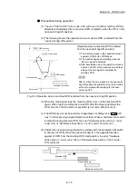
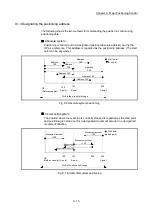
POINTS
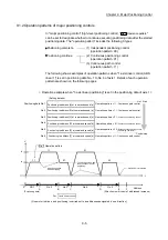
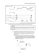
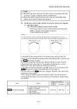
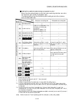
(1) The movement direction is not checked during interpolation operations. Thus, automatic deceleration to a stop will
not be carried out even if the movement direction is changed (See the figures below).
Because of this, the interpolation axis may suddenly reverse direction.
To avoid this sudden direction reversal in the interpolation axis, set the pass point to continuous positioning control
"01" instead of setting it to continuous path control "11".
[Positioning by interpolation]
[Reference axis operation]
[Interpolation axis operation]
Interpola-
tion axis
Positioning data
No.1
Reference axis
Positioning data
No.2
Positioning data No.1 • • • Continuous path control
V
Positioning data
No.1
t
Positioning data
No.2
V
Positioning data
No.1
t
Positioning data
No.2
Suddenly
reverse
direction
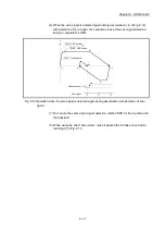
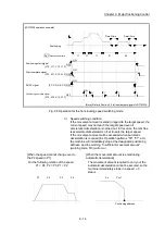
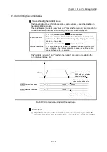
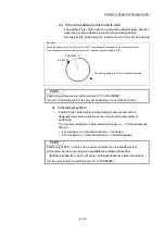
(2) When a "0" is set in the "
Da.6
Positioning address/movement amount
" of the continuous path control positioning data,
the command speed is reduced to 0 in an operation cycle.
When a "0" is set in the "
Da.6
Positioning address/movement amount
" to increase the number of speed change points
in the future, change the "
Da.2
Control method
" to the "NOP" to make the control nonexecutable.
(Refer to Section 9.2.20 "NOP instruction".)
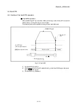
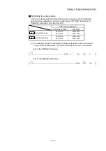
(3) In the continuous path control positioning data, assure a movement distance so that the execution time with that
data is 100 ms or longer, or lower the command speed.
Summary of Contents for MELSEC-L Series
Page 2: ......
Page 30: ...MEMO ...
Page 70: ...2 10 Chapter 2 System Configuration MEMO ...
Page 83: ...3 13 Chapter 3 Specifications and Functions MEMO ...
Page 103: ...3 33 Chapter 3 Specifications and Functions MEMO ...
Page 107: ...3 37 Chapter 3 Specifications and Functions MEMO ...
Page 111: ...3 41 Chapter 3 Specifications and Functions MEMO ...
Page 115: ...3 45 Chapter 3 Specifications and Functions MEMO ...
Page 140: ...4 22 Chapter 4 Installation Wiring and Maintenance of the Product MEMO ...
Page 253: ...5 113 Chapter 5 Data Used for Positioning Control MEMO ...
Page 342: ...5 202 Chapter 5 Data Used for Positioning Control MEMO ...
Page 438: ...7 20 Chapter 7 Memory Configuration and Data Process MEMO ...
Page 440: ...MEMO ...
Page 485: ...9 25 Chapter 9 Major Positioning Control MEMO ...
Page 594: ...9 134 Chapter 9 Major Positioning Control MEMO ...
Page 624: ...10 30 Chapter 10 High Level Positioning Control MEMO ...
Page 656: ...11 32 Chapter 11 Manual Control MEMO ...
Page 690: ...12 34 Chapter 12 Expansion Control MEMO ...
Page 798: ...13 108 Chapter 13 Control Sub Functions MEMO ...
Page 866: ...14 68 Chapter 14 Common Functions MEMO ...
Page 884: ...15 18 Chapter 15 Dedicated Instructions MEMO ...
Page 899: ...16 15 Chapter 16 Troubleshooting MEMO ...
Page 1036: ...Appendix 88 Appendices MEMO ...
Page 1039: ......


